
Automatic moving robot restricting system

A robot and self-moving technology, which is applied to machine parts, manual sweeping machinery, two-dimensional position/channel control, etc., can solve problems such as loss of effectiveness and conveyor failure, and achieve high constraint efficiency

Inactive Publication Date: 2015-12-02
SUZHOU EUP ELECTRIC CO LTD
View PDF7 Cites 5 Cited by
  • Summary
  • Abstract
  • Description
  • Claims
  • Application Information

AI Technical Summary

Problems solved by technology

However, since the above-mentioned portable obstacle signal transmitter needs to continuously transmit signals to the outside, the portable obstacle signal transmitter needs continuous power supply to meet the requirements of transmitting signals. Therefore, if the battery power for the portable obstacle signal transmitter is insufficient or completely If there is no power and the user does not replace the battery in time, the transmitter will not work normally, thus losing the effect of restricting the robot's working range

Method used


Image

  • Automatic moving robot restricting system
  • Automatic moving robot restricting system
  • Automatic moving robot restricting system

Examples


Embodiment 1

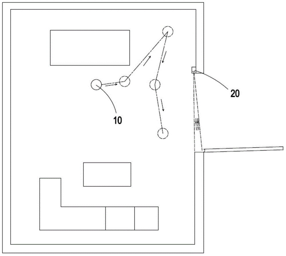
[0040] Such as figure 1As shown, in order to keep the robot working in the room, a self-moving robot control system consisting of a self-moving robot 10 and a portable restraint device 20 is set in the room. Through the cooperation of the robot 10 and the portable restraint device 20 As a result, the robot 10 will not move beyond the door to the outside of the room. The portable restraint device 20 can know whether the robot 10 has moved to the position of the door, so as to decide whether to immediately notify the robot 10 to reverse the moving direction. The robot 10 in this example is a robot for cleaning the ground. The robot 10 is provided with a cleaning module (not shown in the figure), and the cleaning module is used to remove dust on the ground where the robot 10 is located.

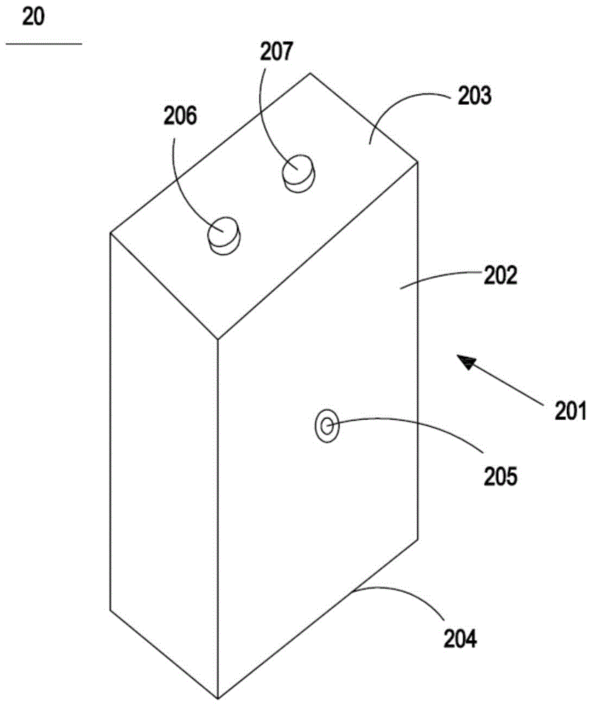
[0041] Such as figure 2 The illustrated portable restraint device 20 includes a base 201 having side walls 202 , a top wall 203 and a bottom wall 204 . The base 201 can be stably supported o...

Embodiment 2

[0054] Such as Figure 10As shown, in the portable restraint device 50, the first directional light receiver 505 is still set up, and a radio wave transmitter 506 is used instead of the second omnidirectional light transmitter 206 in Embodiment 1. The portable restraint device The radio wave transmitter 506 on the device 50 can transmit a radio wave signal 5061 to an external robot, and the radio wave signal 5061 represents a first signal for ordering the robot to execute an avoidance command. At the same time, if Figure 11 As shown, in the robot 60 , a first omnidirectional light transmitter 605 is still provided, and a radio wave receiver 606 matched with the radio wave transmitter 506 is provided on the robot 60 . When the robot 600 moves into the restricted area, after the radio wave signal 5061 emitted by the radio wave transmitter 506 is received by the radio wave receiver 606 on the robot 60, the steering device will be controlled to perform the steps of changing the ...


PUM


Abstract

The invention relates to an automatic moving robot restricting system, and the system comprises a portable restricting device. The portable restricting device comprises a substrate, a first directional light receiver, a signal transmitter, and a first control unit. The first control unit executes a first algorithm, and the first algorithm comprises a step: controlling the signal transmitter to transmit a first signal to the outside when the first directional light receiver receives a directional incident light beam. The system also comprises a robot, and the robot comprises a steering device, a first omnidirectional light transmitter, a signal detector, and a second control unit. The second control unit executes a second algorithm, and the second algorithm comprises a step: controlling the steering device to change the current moving direction of a robot when the signal detector detects the first signal till the signal detector cannot detect the first signal. The device saves more energy in use on the basis of high restricting efficiency.

Description

technical field [0001] The invention relates to a self-moving robot control system. Background technique [0002] At present, self-moving robots are widely used, such as robots that clean the ground, inspection robots that replace manual inspection, etc. When these robots are working, they need to be limited to move within a limited range to perform work. [0003] For example, a robot that cleans the ground will move to another room through the door after completing the cleaning of one room. The usual solution is to close the room door so that the confinement works within that room. Closing the door at that time would cause the user to frequently close the door when entering and leaving the room, thereby causing inconvenience to the user. [0004] A Chinese patent with publication number CN1241080C discloses a method and system for robot positioning and control. The system includes: a portable obstacle signal transmitter, which mainly transmits signals along one axis; The...

Claims


Application Information

Patent Timeline
Patent Type & Authority Applications(China)
IPC IPC(8): G05D1/02A47L11/24A47L11/40
Inventor 卞庄
Owner SUZHOU EUP ELECTRIC CO LTD
Features
  • Generate Ideas
  • Intellectual Property
  • Life Sciences
  • Materials
  • Tech Scout
  • Unparalleled Data Quality
  • Higher Quality Content
  • 60% Fewer Hallucinations
Learn More