Connection device of optical-fiber composite overhead insulated bunched cable and usage method

A bundled cable and overhead insulation technology, applied in the electric power field, can solve the problems of high maintenance costs, achieve low melting point, save cable resources, and prevent short-circuit or burn accidents

Active Publication Date: 2015-12-02
ZHEJIANG CHENGUANG CABLE CO LTD
View PDF7 Cites 2 Cited by
  • Summary
  • Abstract
  • Description
  • Claims
  • Application Information

AI Technical Summary

Problems solved by technology

[0004] But the problem that comes with it is that due to the high integration of cluster cables, the price per unit length is also higher than that of the original cables. When the cluster cable is damaged somewhere, the maintenance cost of replacing the cluster cable is much higher than that of ordinary cables.

Method used


Image

  • Connection device of optical-fiber composite overhead insulated bunched cable and usage method
  • Connection device of optical-fiber composite overhead insulated bunched cable and usage method
  • Connection device of optical-fiber composite overhead insulated bunched cable and usage method

Examples


Embodiment 1

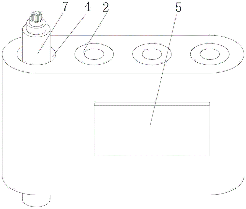
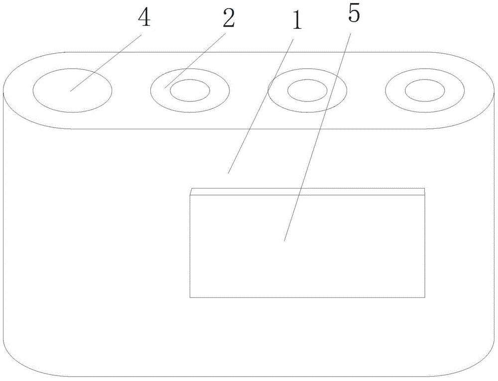
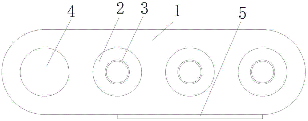
[0026] See Figure 1-4 , the connection device of optical fiber composite overhead insulated bundled cables, including an insulating body 1, a plurality of mutually isolated through holes are arranged on the insulating body 1, and a conductive tube 2 is arranged in each through hole, and the two ends of the conductive tube 2 are flush with the through holes, and conduct electricity. The tube 2 is not exposed outside the insulating body 1 to prevent leakage accidents or short-circuit faults caused by contact with external objects. On this basis, the conductive tube 2 is as long as possible to increase the contact area between the conductive tube 2 and the battery core 8 to reduce resistance. , the conductive tube 2 and the insulating body 1 are separable structures, and the matching conductive tube 2 can be replaced according to the cells 8 of different cross-sectional areas, so that the inner wall of the conductive tube 2 and the cell 8 are interference fit to maximize The con...

Embodiment 2

[0030] See Figure 5, the connection device of optical fiber composite overhead insulated bundled cables, including an insulating body 1, a plurality of mutually isolated through holes are arranged on the insulating body 1, and a conductive tube 2 is arranged in each through hole, and the two ends of the conductive tube 2 are flush with the through holes, and conduct electricity. The tube 2 is not exposed outside the insulating body 1 to prevent leakage accidents or short-circuit faults caused by contact with external objects. On this basis, the conductive tube 2 is as long as possible to increase the contact area between the conductive tube 2 and the battery core 8 to reduce resistance. , the conductive tube 2 and the insulating body 1 are separable structures, and the matching conductive tube 2 can be replaced according to the cells 8 of different cross-sectional areas, so that the inner wall of the conductive tube 2 and the cell 8 are interference fit to maximize The contac...


PUM


Abstract

The invention discloses a connection device of an optical-fiber composite overhead insulated bunched cable and a usage method and belongs to the electric power field. The connection device of the optical-fiber composite overhead insulated bunched cable comprises an insulation body. The insulation body is provided with several through holes which are eradicated with each other. A conductive tube is arranged in each through hole. A conductive soldering flux is arranged in each conductive tube. The insulation body is also provided with a wire hole which can pass through an optical fiber. Through the conductive tubes taking as a medium, electrical cores of two disconnected bunched-cable broken ends are connected, and through the wire hole, a welding optical fiber is protected. Operation is convenient and fast, repeated construction is avoided, cable resources are greatly saved and maintenance cost of the cable is reduced.

Description

technical field [0001] The invention relates to the field of electric power, in particular to a connection device and a using method of an optical fiber composite overhead insulated bundled cable. Background technique [0002] In the past, communication cables and power transmission were constructed separately, and their respective pipes were installed to erect lines. Insulated overhead cables were used for power transmission in the power system. Network cables, telephone lines, and cable TV lines were installed and erected separately by communication departments and network companies, and most of them were repeated construction. , which greatly wastes cable resources and pipeline resources, whether they can be integrated is the key technology currently considered. [0003] The existing technology solves the above problems. For example, the Chinese patent application number 200920104585.6 discloses a fiber optic composite overhead insulated bundled cable, which integrates po...

Claims


Application Information

Patent Timeline
Patent Type & Authority Applications(China)
IPC IPC(8): H01B9/00H01B11/22H01B7/20H01B13/00
Inventor 金金元钱朝辉
Owner ZHEJIANG CHENGUANG CABLE CO LTD
Why Eureka
Try Eureka