Motor, transformer core and manufacturing method thereof

A technology for transformers and motors, which is applied to parts, circuits, and electrical components of transformers/inductors. It can solve problems such as poor magnetic permeability eddy current loss, reduced core efficiency, and reduced magnetic performance of the core, so as to ensure dimensional accuracy and reduce The effect of high loss and magnetic permeability

Inactive Publication Date: 2015-12-02
JINZHOU HALLA ELECTRICAL EQUIP
View PDF8 Cites 0 Cited by
  • Summary
  • Abstract
  • Description
  • Claims
  • Application Information

AI Technical Summary

Problems solved by technology

But there is following deficiency in this structure: 1, because motor iron core is not regular shape, so there will be a large amount of scraps in the process of using monoblock steel sheet punching and shearing into iron core sheet, cause material waste; 2, the iron core sheet of punching and shearing formation It needs to be stacked and riveted together to make an iron core. Because it is stacked and riveted and has a loose lamellar structure, the mechanical strength is not high, and it cannot withstand too much shear force and peeling force, so it is not suitable for use as a stressed member; 3. Punching The dimensional accuracy of the parts after lamination of sheared steel sheets is lower than that of conventional cutting parts, and the parts after lamination of punching and shearing are not suitable for secondary processing
[0003] CN1122527A discloses a powdered iron core that solves the above problems. It adopts the method of mixing and pressing metal powder and insulating powder to make the iron core. This method effectively solves the three shortcomings of the above traditional technology, but this technology introduces The new problem is the problem of the mixing ratio of magnetically conductive metal powder and ceramic insulating powder: if the metal powder has a good magnetic permeability effect, but there will be contact between the metal powder particles, conduction will occur, and eddy current loss will occur after conduction. The efficiency of the iron core is reduced; and if the content of ceramic insulating powder is high, the eddy current loss will be reduced, but the insulating powder is not magnetically conductive, which will lead to a decrease in the magnetic properties of the iron core
These two situations are trade-offs and cannot be achieved at the same time. Compared with the traditional form of punching and riveting, this technology is inferior in both magnetic permeability and eddy current loss, which is the main reason why this technology cannot be promoted.

Method used


Image

  • Motor, transformer core and manufacturing method thereof
  • Motor, transformer core and manufacturing method thereof
  • Motor, transformer core and manufacturing method thereof

Examples


Embodiment 1

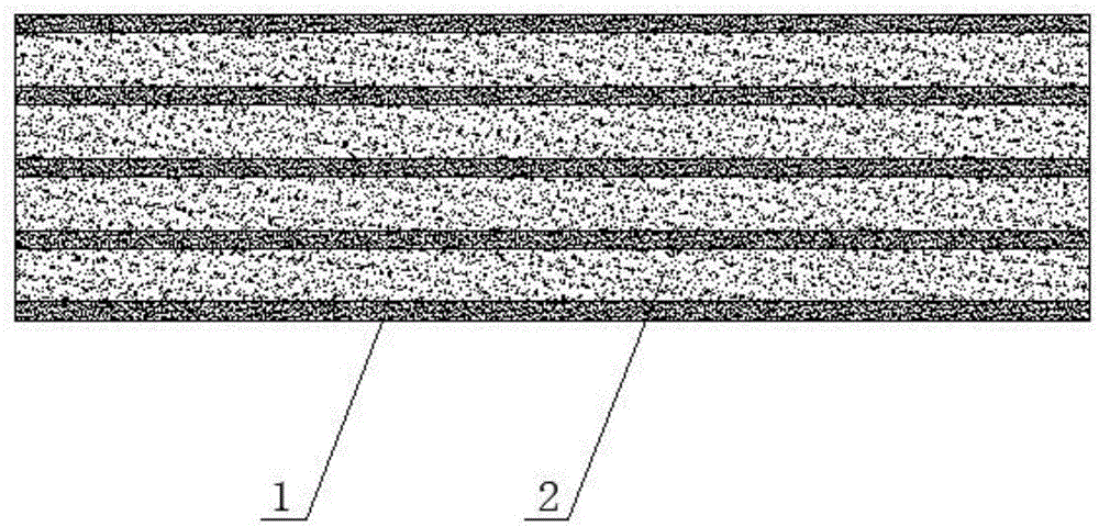
[0030] As shown in the figure, the motor iron core and the transformer iron core are composed of multi-layer dense solid layers 2 of magnetically conductive metal powder and dense solid layers 1 of multi-layer ceramic insulating powder. The dense solid layers 2 of magnetically conductive metal powder and ceramic insulating powder The dense solid layer 1 is distributed from bottom to top at intervals. In this embodiment, the number of layers of the dense solid layer 2 of magnetically conductive metal powder is 4 layers, and the number of layers of dense solid layer 1 of ceramic insulating powder is 5 layers. The top layer is a dense solid layer 1 of ceramic insulating powder, the thickness of the dense solid layer 2 of magnetically permeable metal powder is 0.1mm-0.8mm, and the thickness of the dense solid layer 1 of ceramic insulating powder is 0.02mm-0.1mm.

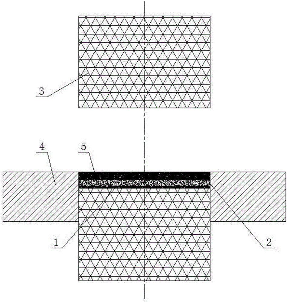
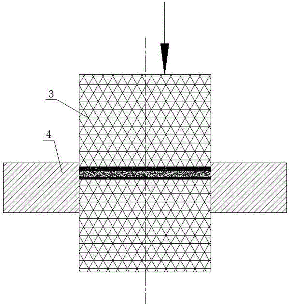
[0031] The manufacturing method of the motor iron core and the transformer iron core comprises the following steps:

...

Embodiment 2

[0038] The motor iron core and the transformer iron core are alternately composed of multi-layer dense solid layers 2 of magnetically conductive metal powder and dense solid layers 1 of multi-layer ceramic insulating powder, and the dense solid layers 2 of magnetically conductive metal powder and dense solid layers 1 of ceramic insulating powder are composed of Distributed at intervals from bottom to top, in this embodiment, the number of layers of the dense solid layer 2 of magnetically conductive metal powder is 10 layers, the number of layers of dense solid layer 1 of ceramic insulating powder is 11 layers, and the bottom and top layers of the iron core are both ceramic insulation Powder dense solid layer 1, the thickness of ceramic insulating powder dense solid layer 1 is 0.03mm, the working pressure of the press is 700MPa, the thickness of magnetically conductive metal powder dense solid layer 2 is 0.1mm, the working pressure of the press is 700MPa, the finished product Th...

Embodiment 3

[0040] The motor iron core and the transformer iron core are alternately composed of multi-layer dense solid layers 2 of magnetically conductive metal powder and dense solid layers 1 of multi-layer ceramic insulating powder, and the dense solid layers 2 of magnetically conductive metal powder and dense solid layers 1 of ceramic insulating powder are composed of Distributed at intervals from bottom to top, in this embodiment, the number of layers of the dense solid layer 2 of magnetically conductive metal powder is 3 layers, the number of layers of dense solid layer 1 of ceramic insulating powder is 4 layers, and the bottom and top layers of the core are both ceramic insulating Powder dense solid layer 1, the thickness of ceramic insulating powder dense solid layer 1 is 0.1mm, the working pressure of the press is 800MPa, the thickness of magnetically conductive metal powder dense solid layer 2 is 0.8mm, the working pressure of the press is 800MPa, the finished product The height...


PUM

PropertyMeasurementUnit
thicknessaaaaaaaaaa
thicknessaaaaaaaaaa
thicknessaaaaaaaaaa

Abstract

The invention relates to a motor, a transformation core and a manufacturing method of the transformation core. The transformation core is characterized by being composed of a plurality of magnetic conduction metal powder compact solid layers and a plurality of ceramic insulation powder compact solid layers, the magnetic conduction metal powder compact solid layers and the ceramic insulation powder compact solid layers are alternately distributed from bottom to top at intervals, and the bottommost layer and the topmost layer of the core are the ceramic insulation powder compact solid layers. The transformer core is high in material utilization rate, high in mechanical strength, high in size precision, small in eddy current loss and high in magnetic permeability.

Description

technical field [0001] The invention relates to the field of electric engineering, in particular to a motor, a transformer core and a manufacturing method thereof. Background technique [0002] At present, most motor cores and transformer cores are made of magnetically permeable steel sheets laminated with insulating layers between the steel sheets. Motors and transformer cores rely on this structure to weaken the eddy current inside the metal magnetic conduction mechanism caused by being in an alternating magnetic field. But there is following deficiency in this structure: 1, because motor iron core is not regular shape, so there will be a large amount of scraps in the process of using monoblock steel sheet punching and shearing into iron core sheet, cause material waste; 2, the iron core sheet of punching and shearing formation It needs to be stacked and riveted together to make an iron core. Because it is stacked and riveted and has a loose lamellar structure, the mechan...

Claims


Application Information

Patent Timeline
Patent Type & Authority Applications(China)
IPC IPC(8): H01F3/08H01F27/255H02K1/02
Inventor 陈鹏王健张巍
Owner JINZHOU HALLA ELECTRICAL EQUIP
Why Eureka
Try Eureka