Spacer stacked riveted motor iron core and its manufacturing method and device dedicated to the method
A manufacturing method and iron core technology, applied in the manufacture of stator/rotor body, magnetic circuit shape/style/structure, etc., can solve the problems of reduced motor efficiency, poor shape, etc., and achieve the effect of full annealing
- Summary
- Abstract
- Description
- Claims
- Application Information
AI Technical Summary
Problems solved by technology
Method used
Image
Examples
Embodiment 1
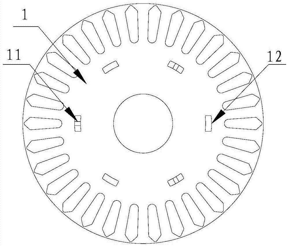
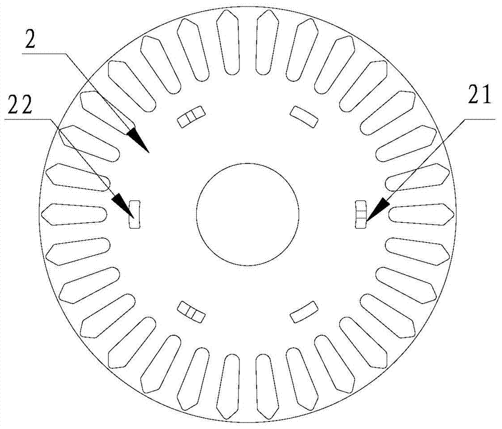
[0030] Embodiment 1 The spacer stacked riveted motor iron core according to the present invention includes an iron core body, and the iron core body includes a plurality of first punching pieces 1, a plurality of second punching pieces 2 and a piece for layering The end face punching piece, the first punching piece 1 is provided with a plurality of first riveting point bosses 11 and a plurality of first riveting through holes 12, and the second punching piece 2 is provided with a plurality of second The riveting point boss 21 and a plurality of second riveting holes 22, the first riveting point boss 11 and the first riveting hole 12, the second riveting point boss 21 and the The second riveting holes 22 are alternately arranged on concentric circles with the center of the first punching piece 1 and the center of the second punching piece 2 as the center, and the first riveting point boss 11 is connected with the second riveting hole. Corresponding to the hole 22, the second ri...
Embodiment 2
[0035] Embodiment 2 The method for manufacturing the diaphragm-stacked riveted motor core described in Embodiment 1 includes the following steps:
[0036] 1) When feeding material for the first time, the central controller controls to send instructions to the first cylinder 4 and the second cylinder 5, and the first cylinder 4 and the second cylinder 5 accept the instructions to perform corresponding actions: the first cylinder 4 draws out the first pumping plate 41, The first cylinder 4 is in the state of the punching point boss, that is, the die punch of the first cylinder 4 punches out the first riveting point boss 11 on the first punching sheet 1, and the second cylinder 5 is drawn into the second pumping plate 51 at the same time , so that the second cylinder 5 is in the state of punching through holes, and the second cylinder 5 punches out the first riveting through hole 12 on the same first punching sheet 1; It is the state of punching through holes;
[0037] 2) During...
Embodiment 3
[0041]Embodiment 3 Utilize the special-purpose device that the manufacturing method described in embodiment 2 is constructed, comprise at least one group of air cylinders, conveyor belt and central controller, each group of air cylinders all comprises a first air cylinder 4 and a second air cylinder 5, wherein The cylinders of the group are arranged above the conveyor belt and arranged along the conveyor belt, and the first cylinder 4 and the second cylinder 5 are respectively equipped with corresponding first pumping plates 41 and second pumping plates 51; the die punches of the first cylinder 4 Corresponding to the position of the first riveting point boss 11 of the first punching piece 1, the die punch of the second cylinder 5 of the same group corresponds to the position of the second riveting point boss 21 of the second punching piece 2; all the first cylinders 4. The control terminals of the second cylinder 5 are respectively connected to the corresponding control termina...
PUM
 Abstract
Description
Claims
Application Information
 - R&D
- Intellectual Property
- Life Sciences
- Materials
- Tech Scout
- Unparalleled Data Quality
- Higher Quality Content
- 60% Fewer Hallucinations
Browse by: Latest US Patents, China's latest patents, Technical Efficacy Thesaurus, Application Domain, Technology Topic, Popular Technical Reports.
© 2025 PatSnap. All rights reserved.Legal|Privacy policy|Modern Slavery Act Transparency Statement|Sitemap|About US| Contact US: help@patsnap.com


