Synchronous rectification control method and circuit

A technology of synchronous rectification and control method, which is applied in the direction of converting AC power input to DC power output, electrical components, and output power conversion devices, which can solve the problems of easy error in output voltage detection and difficult to accurately turn off the current of synchronous rectification circuit. , to achieve the accurate effect of primary edge detection

Active Publication Date: 2015-12-02
SILERGY SEMICON TECH (HANGZHOU) CO LTD
View PDF5 Cites 23 Cited by
  • Summary
  • Abstract
  • Description
  • Claims
  • Application Information

AI Technical Summary

Problems solved by technology

[0005] In view of this, the object of the present invention is to provide a synchronous rectification control method and a synchronous rectification circuit to solve the techn

Method used


Image

  • Synchronous rectification control method and circuit
  • Synchronous rectification control method and circuit
  • Synchronous rectification control method and circuit

Examples


Embodiment Construction

[0027] Preferred embodiments of the present invention will be described in detail below with reference to the accompanying drawings, but the present invention is not limited to these embodiments. The present invention covers any alternatives, modifications, equivalent methods and schemes made within the spirit and scope of the present invention.

[0028] In order to provide the public with a thorough understanding of the present invention, specific details are set forth in the following preferred embodiments of the present invention, but those skilled in the art can fully understand the present invention without the description of these details.

[0029] In the following paragraphs the invention is described more specifically by way of example with reference to the accompanying drawings. It should be noted that all the drawings are in simplified form and use inaccurate scales, which are only used to facilitate and clearly assist the purpose of illustrating the embodiments of t...


PUM


Abstract

The invention discloses a synchronous rectification control method and circuit, and the method comprises a plurality of working steps. At a later working stage of synchronous rectification, a drain-source voltage rises to a closed-loop threshold voltage along with the decrease of a current, and a grid-source voltage starts to decrease, thereby enabling conduction resistance to increase. Through enabling a drain-source voltage of a synchronous rectification tube to be close to a reference voltage, the drain-source voltage remains equal to the closed-loop threshold voltage. Therefore, the drain-source voltage remains unchanged in a later period of synchronous rectification conduction, and primary side detection is enabled to be more accurate. Meanwhile, a grid-source switching-off threshold voltage is used for judging the switching-off time, thereby guaranteeing that the synchronous rectification tube is precisely switched off at a moment of current zero crossing.

Description

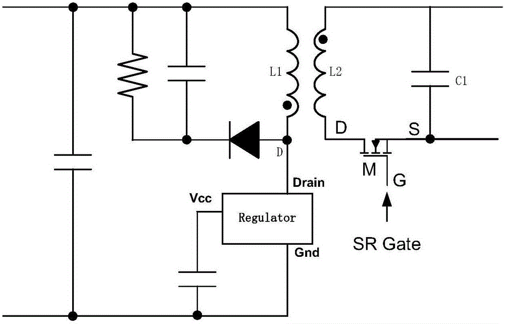
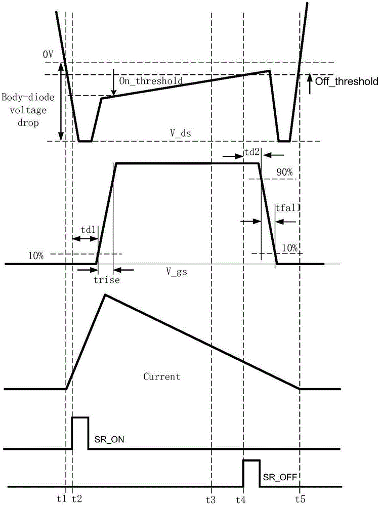
technical field [0001] The invention relates to the technical field of power electronics, in particular to a synchronous rectification control method and a synchronous rectification circuit. Background technique [0002] Synchronous rectification is a method of replacing rectifier diodes with power MOSFETs with low on-state resistance to reduce rectification losses. figure 1 The synchronous rectification circuit based on the flyback topology in the prior art is listed in , including a transformer composed of a primary inductor L1 and a secondary inductor L2, an output capacitor C1, and a synchronous rectifier M, and D, S, and G represent synchronous rectifiers respectively. The drain, source and gate of M, Regulator is the main power switch tube of the flyback topology. figure 2 for with figure 1 In the corresponding working waveform diagram, V_ds is the drain-source voltage of the synchronous rectifier M, and V_gs is the gate-source voltage of the synchronous rectifier M...

Claims


Application Information

Patent Timeline
IPC IPC(8): H02M7/217
Inventor 李新磊徐孝如白永江张少斌
Owner SILERGY SEMICON TECH (HANGZHOU) CO LTD
Why Eureka
Try Eureka