A control circuit of a boost converter

A boost converter and control circuit technology, applied in control/regulation systems, DC power input conversion to DC power output, instruments, etc., can solve the problems of bulk diode loss, insufficient real-time tracking of energy harvesters, etc.

Active Publication Date: 2015-08-19
ZHEJIANG UNIV
View PDF4 Cites 0 Cited by
  • Summary
  • Abstract
  • Description
  • Claims
  • Application Information

AI Technical Summary

Problems solved by technology

The disadvantage is that the MPPT scheme adopted by the system is not enough to track the changes in the working conditions of the energy harvester in real time, and the zero-current shutdown scheme adopted will still cause large body diode losses

Method used


Image

  • A control circuit of a boost converter
  • A control circuit of a boost converter
  • A control circuit of a boost converter

Examples


Embodiment Construction

[0056] In order to describe the present invention more specifically, the technical solution and related principles of the present invention will be described in detail below in conjunction with the accompanying drawings and specific embodiments.

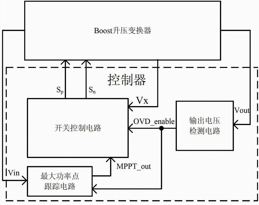
[0057] Such as figure 1 As shown, a control circuit of a Boost boost converter includes an output voltage detection unit, a maximum power tracking unit and a switch control unit; wherein,

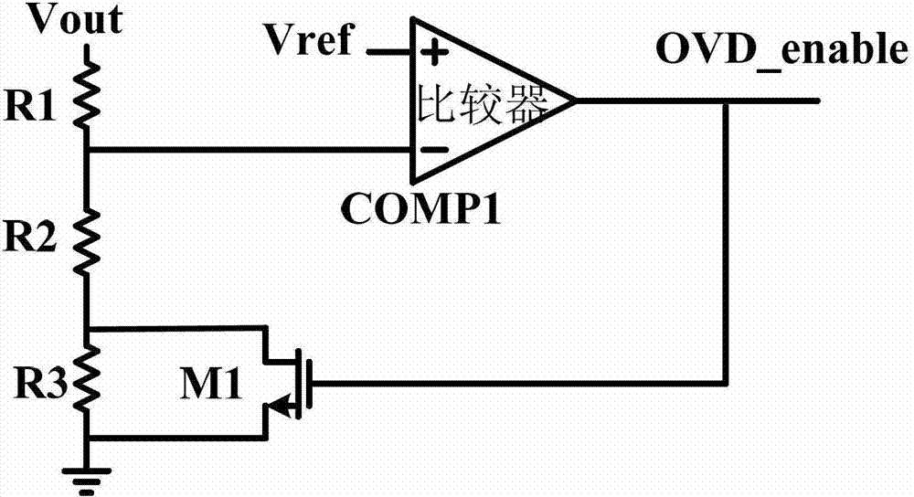
[0058] Such as image 3 As shown, the output voltage detection unit includes three resistors R1-R3, a comparator COMP1 and a MOS transistor M1. Among them, the resistors R1-R3 are connected in series in sequence, the output voltage Vout is connected to one end of the resistor R1, the other end of the resistor R1 is connected to the inverting input terminal of the comparator COMP1, and the output terminal of the comparator COMP1 is connected to the gate of the MOS transistor M1 And as an output port of the enable control signal OVD_enable, one e...


PUM


Abstract

The invention discloses a control circuit for a Boost converter, which comprises an output voltage detection unit, a maximum power tracking unit and a switch control unit, wherein the switch control unit comprises a zero-current switch-off module, an MPPT (Maximum Power Point Tracking) control module, an Sn generating module and an Sp generating module. According to the control circuit, the converting efficiency of the Boost converter is increased greatly via the output voltage detection unit; accurate zero current switch-off is realized through the zero current switch-off module, so that the efficiency of the Boost converter is increased; real-time monitoring of the input power is realized through the maximum power point tracking unit, and the Boost converter starts working when the input voltage reaches a maximum input power point, so that the Boost converter can be suitable for new energy power supplies with maximum power output points such as solar circuit boards; and the switch-on time is not influenced by the temperature and a chip corner angle by a constant switch-on time generating circuit, so that the stability of the system is enhanced.

Description

technical field [0001] The invention relates to the technical field of electronic circuits, in particular to a control circuit of a Boost converter. Background technique [0002] Due to the limited stock of conventional fossil fuels such as oil and natural gas and the high cost of the environment, the use of renewable energy such as solar energy, wind energy, and bioenergy as much as possible is an effective measure to protect the atmospheric environment on which human beings depend. . [0003] With the continuous development of energy harvesting technology, the collection and utilization of micro-power waste energy has begun to come into people's field of vision in recent years. How to convert waste energy into electrical energy and provide it to different types of electronic instruments and products is an important issue for electronics and semiconductors. An important topic for the industry to develop green energy applications. [0004] Converting ambient energy into el...

Claims


Application Information

Patent Timeline
Patent Type & Authority Patents(China)
IPC IPC(8): H02M3/155
Inventor 王璐赵梦恋黄毳晨之张佳吴晓波张浩洲方瑜骅
Owner ZHEJIANG UNIV
Why Eureka
Try Eureka