Production device and production method for chopped glass strands
A technology of chopped strands and glass fibers, which is applied in glass manufacturing equipment, manufacturing tools, textiles and papermaking, etc., and can solve problems such as inability to discharge, poor cutting of glass strands, and narrowed intervals between cutting blades.
- Summary
- Abstract
- Description
- Claims
- Application Information
AI Technical Summary
Problems solved by technology
Method used
Image

Examples
no. 1 approach
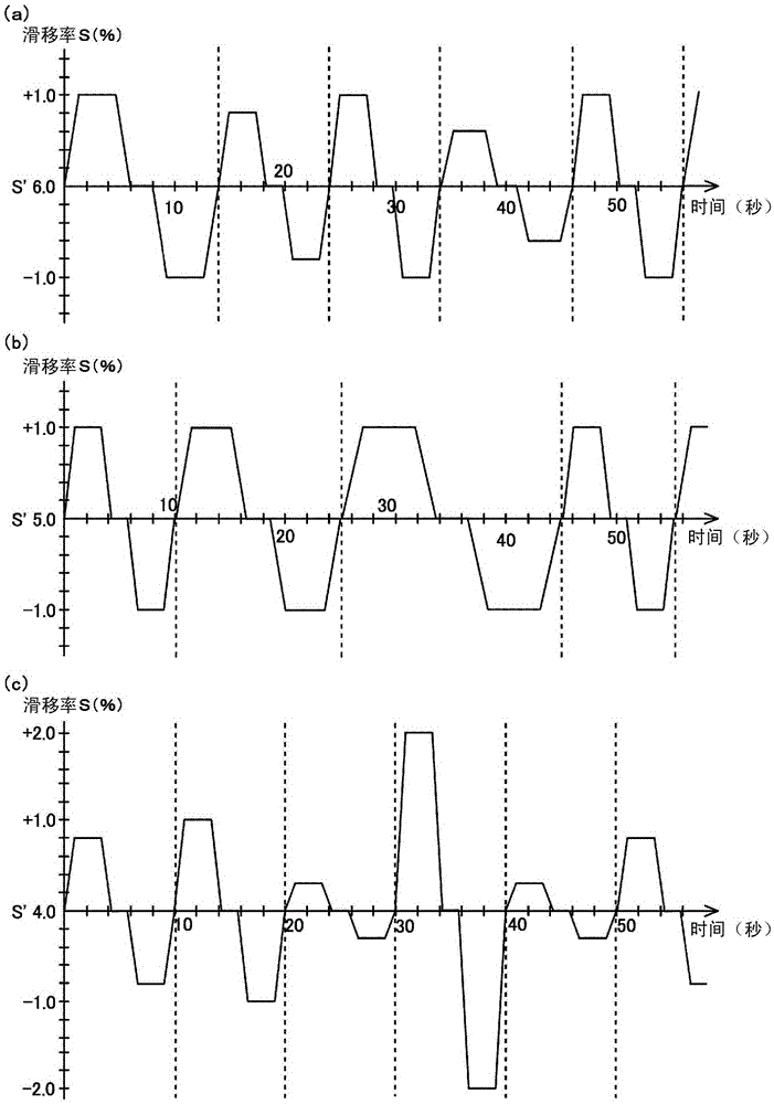
[0076] exist image 3 In the first embodiment shown in (a), the slip ratio S is randomly varied using both the first variation method and the second variation method. Each interval in the timing chart demarcated by a dotted line represents one period of fluctuation of the slip ratio S. FIG. Set the reference slip ratio S' to 6.0%, and make the slip ratio S fluctuate randomly from the reference slip ratio S' with a fluctuation amount of ±0.6 to ±1.0%. The variable time period is randomly changed between 10 seconds and 14 seconds. In the present embodiment, since both the vertical fluctuation amount of the slip ratio S and the time period of the fluctuation are randomly varied or changed, the cutting blade 10 a of the cutter roll 10 can be rotated with respect to the surface 11 a of the rubber roll 11 before and after rotation. Abutting states randomly staggered in direction. As a result, deep grooves can be reliably prevented from being formed on the surface 11 a of the rubb...
no. 2 approach
[0078] exist image 3 In the second embodiment shown in (b), the vertical fluctuation amount of the slip ratio S is set to be fixed, and the time period during which the slip ratio S fluctuates is randomly changed using the second fluctuation method. Each section demarcated by a dotted line in the timing chart represents one cycle in which the slip ratio S fluctuates. Set the reference slip ratio S' to 5.0%, and make the slip ratio S fluctuate with ±1.0% up and down variation from the reference slip ratio S', and make the time period of the slip ratio S change within 10 Seconds to 22 seconds are randomly changed. In the present embodiment, since the time period of the fluctuation of the slip ratio S is randomly changed, the cutting blade 10 a of the cutter roll 10 can be offset in a state randomly shifted in the front and rear directions of rotation with respect to the surface 11 a of the rubber roll 11 . catch. As a result, deep grooves can be reliably prevented from being...
no. 3 approach
[0080] exist image 3 In the third embodiment shown in (c), the time period of the fluctuation of the slip ratio S is set to be fixed, and the vertical fluctuation amount of the slip ratio S is randomly fluctuated using the first fluctuation method. Each interval in the timing chart demarcated by a dotted line represents one period of fluctuation of the slip ratio S. FIG. The reference slip ratio S' is set to 4.0%, and the slip ratio S is randomly fluctuated from the reference slip ratio S' with a fluctuation amount of ±0.4 to ±2.0%, and the fluctuation of the slip ratio S The time period is set to 10 seconds. In the present embodiment, since the vertical fluctuation amount of the slip ratio S is randomly varied, the cutting blade 10a of the cutter roller 10 can be brought into contact with the surface 11a of the rubber roller 11 in a state of being randomly shifted in the front-rear direction of rotation. . As a result, deep grooves can be reliably prevented from being for...
PUM
| Property | Measurement | Unit |
|---|---|---|
| diameter | aaaaa | aaaaa |
| length | aaaaa | aaaaa |
| thickness | aaaaa | aaaaa |
Abstract
Description
Claims
Application Information
 - R&D
- Intellectual Property
- Life Sciences
- Materials
- Tech Scout
- Unparalleled Data Quality
- Higher Quality Content
- 60% Fewer Hallucinations
Browse by: Latest US Patents, China's latest patents, Technical Efficacy Thesaurus, Application Domain, Technology Topic, Popular Technical Reports.
© 2025 PatSnap. All rights reserved.Legal|Privacy policy|Modern Slavery Act Transparency Statement|Sitemap|About US| Contact US: help@patsnap.com