Novel surgical instrument with multiple sections being bendable after adjusting
A technology of surgical instruments and bending adjustment, which is applied in the direction of surgery, surgical instruments, obstetrics and gynecology instruments, etc. It can solve the problems of non-adjustable angle, non-rotation, and non-rotation of instruments, so as to reduce mutual collision and interference, and the structure is simple and reasonable , The effect of safe operation
- Summary
- Abstract
- Description
- Claims
- Application Information
AI Technical Summary
Problems solved by technology
Method used
Image
Examples
specific Embodiment 1
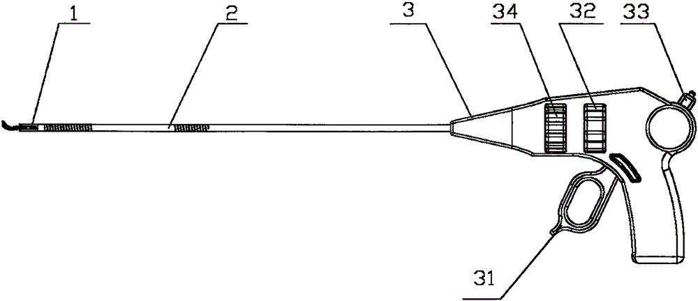
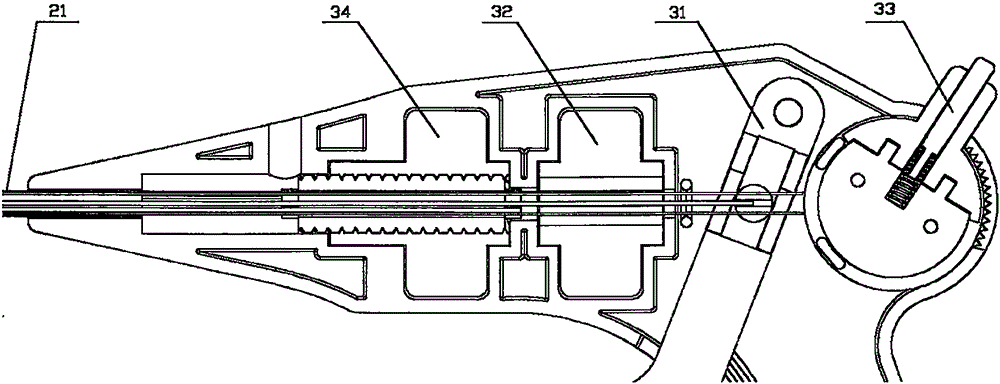
[0042] Such as figure 1 As shown in -7, a novel multi-segment adjustable curved surgical instrument includes a functional instrument assembly 1, an instrument shaft 2 and a control handle 3 arranged at the proximal end of the surgical instrument, and the functional instrument assembly 1 includes a base 11 and a functional instrument 12, the instrument shaft 2 includes an outer tube 21, a functional instrument control part 22, and a bending control wire 23, the distal end of the outer tube 21 is connected to the base 11, and the functional instrument control part The distal end of 22 is connected to the functional instrument 12, the proximal end of the functional instrument control part 22 is connected to the control handle 3, and the functional instrument control part 22 is bendable, preferably made of a flexible material. The control handle 3 includes a functional instrument operating part 31, a rotating operating part 32 and a bending control wire operating part 33. The prox...
specific Embodiment 2
[0048] The structure of the surgical instrument in this embodiment is basically the same as that in the first embodiment, the difference is that, as Figure 5c-5d As shown, the middle part of the outer tube 21 is provided with one or more bendable segments 211, and the distal end of the outer tube is a rigid segment. Such as Figures 11a-11b As shown, the proximal end of the bending angle adjustment unit 24 is fixedly connected to the rotary operating member 32, and the rotating operating member 32 can limit the axial movement of the bending angle adjusting unit 24, and the outer tube 21 and the adjusting The bending adjustment auxiliary part 341 of the bending operation part 34 is connected, and the bending adjustment auxiliary part 341 of the bending adjustment operation part 34 can drive the outer tube 21 to move axially. A rotating auxiliary part 321 is arranged on the rotating operating part 32, and the rotating auxiliary part 321 is connected with the bending adjusting ...
specific Embodiment 3
[0051] The structure of the surgical instrument of this embodiment is basically the same as that of the surgical instrument in the specific embodiment 1, the difference is that, as Figure 13aAs shown, the functional device assembly 1 does not include a base, the distal end of the bending control wire 23 is fixedly connected to the distal end of the outer tube 21, and the distal end of the outer tube 21 is provided with a bendable section 211 , the adjacent portion of the bendable section 211 is a rigid straight section 212 , and the distal end bend adjustment of the outer tube 21 can be realized by operating the bend adjustment control wire operating member 33 . The connection and operation methods of the outer tube 21 , the bending angle adjusting unit 24 , the bending adjustment operating member 34 and the rotating operating member 32 are completely the same as those of the surgical instrument in the first embodiment.
[0052] In a preferred embodiment, as Figure 13b As s...
PUM
 Abstract
Description
Claims
Application Information
 - R&D
- Intellectual Property
- Life Sciences
- Materials
- Tech Scout
- Unparalleled Data Quality
- Higher Quality Content
- 60% Fewer Hallucinations
Browse by: Latest US Patents, China's latest patents, Technical Efficacy Thesaurus, Application Domain, Technology Topic, Popular Technical Reports.
© 2025 PatSnap. All rights reserved.Legal|Privacy policy|Modern Slavery Act Transparency Statement|Sitemap|About US| Contact US: help@patsnap.com


