Air dust removal device for radiator and harvester
A technology of air dust removal and radiator, which is applied to harvesters, dust removal, dispersing particle filtration, etc. It can solve the problem that the dust cover affects the passability of the whole machine, and achieve the requirements of ensuring the design height, saving maintenance time, and improving performance. Effect
- Summary
- Abstract
- Description
- Claims
- Application Information
AI Technical Summary
Problems solved by technology
Method used
Image

Examples
Embodiment 1
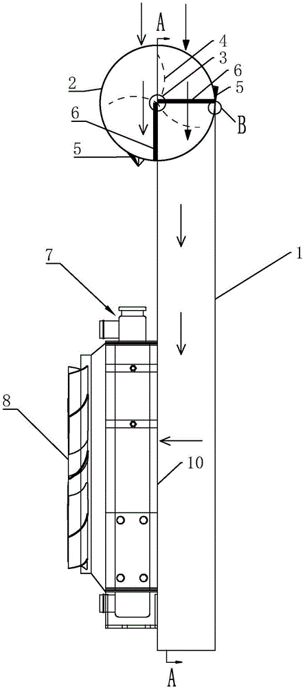
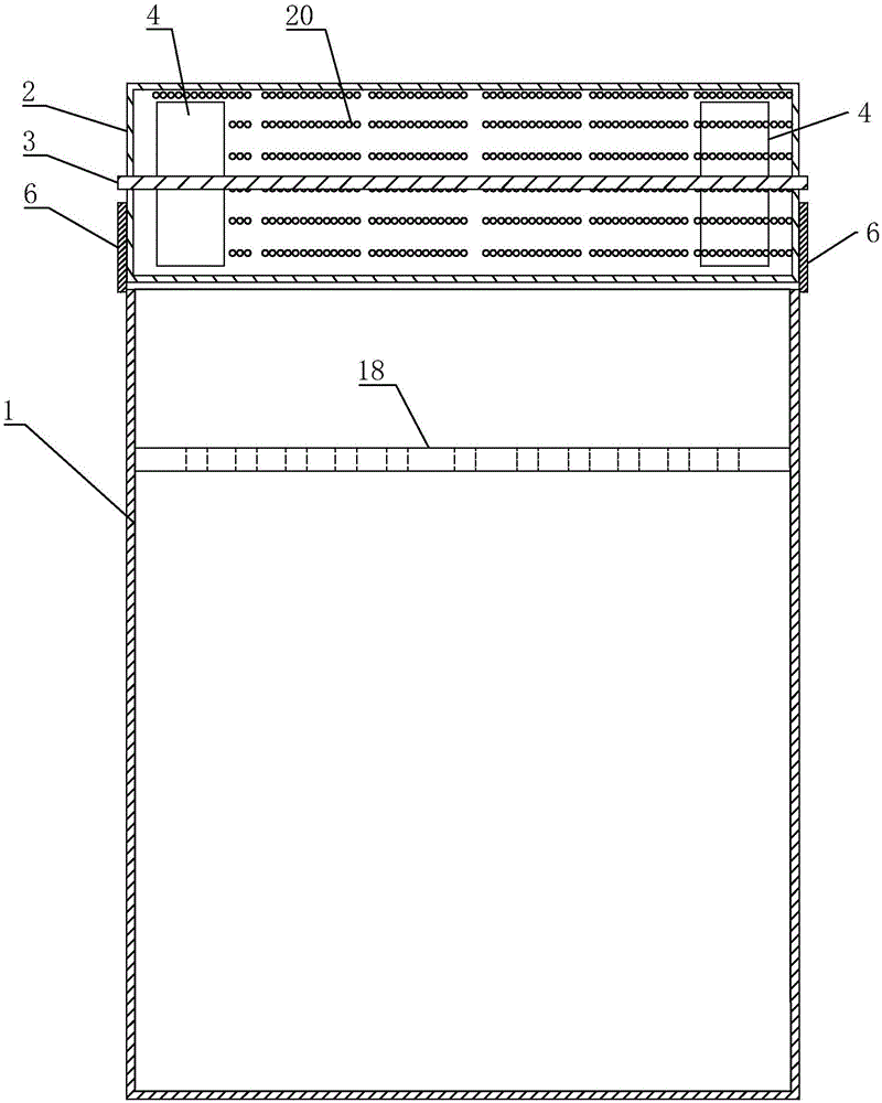
[0036] Such as Figure 1 to Figure 3 Commonly shown in , a radiator air dust removal device includes a vertically arranged wind guide cover 1 with an open upper end. One side of the wind guide cover 1 is provided with an air outlet 10. When installed on the equipment, the air outlet 10 is located On the side of the device 7 away from the suction fan, the upper opening of the air guide cover 1 is correspondingly provided with a dust removal screen cover, and the dust removal screen cover covers the upper end opening of the air guide cover, such as figure 2 As shown in , the dust removal net cover can preferably be a cylinder structure, so that the axial extension direction of the cylinder body 2 is perpendicular to the vertical extension direction of the air guide cover 1, and both ends of the cylinder body 2 in the axial direction are closed, The outer peripheral surface of cylinder body 2 is net cover structure, and is provided with the first hairbrush 5 that is used to clea...
Embodiment 2
[0045] The structure of this embodiment is basically the same as that of Embodiment 1, the difference is that:
[0046] Such as Figure 4 and Figure 5 Commonly shown in , the rotating shaft 3 is fixedly arranged on the outer surface of the cylinder 2 and arranged along the axial direction of the cylinder 2 , and the fan blades 4 are arranged outside the cylinder 2 at this time.
[0047] The specific working process of the above-mentioned embodiment 1 and embodiment 2 is: the above-mentioned dust removal net cover can be selected to be provided with some mesh structures distributed along the circumferential direction on the surface of the cylinder 2, or a structure of interwoven wire weaving can be used, and the suction fan can be selected. Be the cooling fan 7 of engine, certainly also can be set to simple suction fan.
[0048] Such as figure 1 and Figure 4 As shown in , the arrow represents the flow direction of the air, and the solid arrow represents the flow direction...
Embodiment 3
[0053] The structure of this embodiment is basically the same as that of Embodiment 1, the difference is that:
[0054] Such as Figure 6 and Figure 7 Commonly shown, the dust removal screen cover is a cylinder 11, the axial extension direction of the cylinder body is parallel to the vertical extension direction of the wind guide cover 9, and the end faces of the two ends of the cylinder body 9 in the axial direction are the screen cover 110 structure, the outer circumferential surface of the cylinder 2 is a closed structure.
[0055] The rotating shaft 12 is arranged at the center of the cylinder 11 and arranged along the axial direction of the cylinder 11, and the two ends of the cylinder 11 are fixed on the rotating shaft 12, and the fan blades 13 are arranged on the rotating shaft 12 and located inside the cylinder 11, the second A brush 14 is arranged around the net cover 110 at the end of the cylinder and is tangent to the end surface of the net cover 110 .
[0056] ...
PUM
 Abstract
Description
Claims
Application Information
 - R&D
- Intellectual Property
- Life Sciences
- Materials
- Tech Scout
- Unparalleled Data Quality
- Higher Quality Content
- 60% Fewer Hallucinations
Browse by: Latest US Patents, China's latest patents, Technical Efficacy Thesaurus, Application Domain, Technology Topic, Popular Technical Reports.
© 2025 PatSnap. All rights reserved.Legal|Privacy policy|Modern Slavery Act Transparency Statement|Sitemap|About US| Contact US: help@patsnap.com