Technology design method for milling curve surface of cold-working-die steel spliced piece at high speed
A cold work die steel, high-speed milling technology, applied in milling machine equipment, milling machine equipment details, metal processing equipment and other directions, can solve the problem of conflict between machining efficiency and machined surface quality, and achieve the effect of solving the conflict between machining efficiency and machined surface quality
- Summary
- Abstract
- Description
- Claims
- Application Information
AI Technical Summary
Problems solved by technology
Method used
Image
Examples
specific Embodiment approach 1
[0072] Specific implementation mode 1: Experimental formula for surface roughness in high-speed milling Cr12MoV and 7CrSiMnMoV
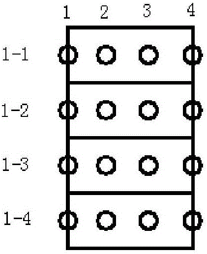
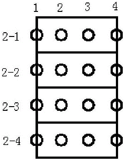
[0073] (1) Using two indexable ball-end milling cutters with a diameter of 20mm and two teeth, the high-speed milling experiments of Cr12MoV and 7CrSiMnMoV were carried out on the MIKRONUCP710 five-axis CNC machining center; among them, the overhang of the milling cutter was 92mm, and the feed rate per tooth It is 0.3mm / z, the milling line spacing is 0.3mm, the milling depth is 0.2mm, and the inclination angle of milling cutter is 15°;
[0074] (2) The hardness test methods of Cr12MoV hardened steel and 7CrSiMnMoV specimens, and the cutting experiment plan are as follows: figure 1 , figure 2 And as shown in Table 1 and Table 2:
[0075] Table 1 Cr12MoV experimental scheme
[0076]
[0077] Table 27 CrSiMnMoV experimental scheme
[0078]
[0079] (3) Surface roughness R of Cr12MoV and 7CrSiMnMoV specimens processed along the line spacing di...
specific Embodiment approach 2
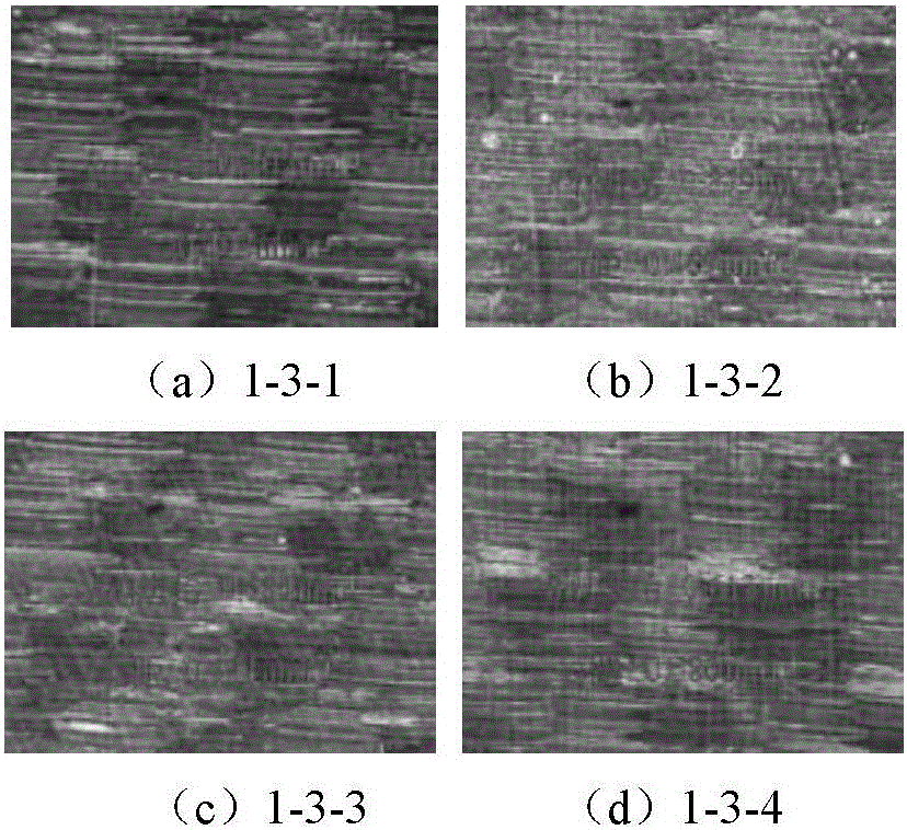
[0092] Specific implementation mode 2: Surface morphology experiment of high-speed milling Cr12MoV and 7CrSiMnMoV splicing parts
[0093] (1) Two materials with different hardnesses, Cr12MoV and 7CrSiMnMoV, are spliced into a multi-hardness distribution specimen with a large hardness gradient. The hardness test method and cutting experiment plan of the specimen are as follows: Figure 5 and Table 5;
[0094] Table 5 Hardness test results of multi-hard reading splicing specimens
[0095]
[0096]
[0097] (2) A high-speed milling experiment was carried out on a MIKRONUCP710 five-axis CNC machining center with a two-tooth indexable ball-end milling cutter with a diameter of 20mm. Among them, the overhang of the milling cutter is 92mm, the feed rate per tooth is 0.3mm / z, the milling line spacing is 0.3mm, the milling depth is 0.2mm, and the inclination angle of the milling cutter is 15°;
[0098] (3) The surface roughness test results of Cr12MoV and 7CrSiMnMoV splicing sp...
specific Embodiment approach 3
[0107] Specific implementation method three: Experimental plan for high-speed milling of Cr12MoV and 7CrSiMnMoV curved surface splices
[0108] (1) Using a high-speed ball-end milling cutter to conduct high-speed milling experiments on Cr12MoV hardened steel and 7CrSiMnMoV curved surfaces on a MIKRONUCP710 five-axis CNC machining center; the model of the tool holder is BNMM-200075T-S20, the model of the blade is JC8003, and the number of teeth 2, the diameter of the milling cutter is 20mm, the overhang of the milling cutter is 100mm; the rotational speed of the milling cutter is 8000rpm, the feed rate is 4000mm / min, the milling line spacing is 0.3mm, and the milling depth is 0.2mm;
[0109] (2) Cr12MoV and 7CrSiMnMoV surface splicing specimens such as Figure 12 As shown; the size of the test piece is 100×48×50mm, the machined surface along the width direction is a ruled surface, and the machined surface along the length direction is a sinusoidal shape connected by curved surf...
PUM
 Abstract
Description
Claims
Application Information
 - R&D
- Intellectual Property
- Life Sciences
- Materials
- Tech Scout
- Unparalleled Data Quality
- Higher Quality Content
- 60% Fewer Hallucinations
Browse by: Latest US Patents, China's latest patents, Technical Efficacy Thesaurus, Application Domain, Technology Topic, Popular Technical Reports.
© 2025 PatSnap. All rights reserved.Legal|Privacy policy|Modern Slavery Act Transparency Statement|Sitemap|About US| Contact US: help@patsnap.com


