
Cushion structure used for inside of package box and package structure

A technology of buffer structure and packaging structure, applied in packaging, packaging food, packaging protection and other directions, can solve the problems of only overall replacement, high use cost, and contamination of liquid crystal products, and achieves the effect of good cooperation firmness and low use cost.

Active Publication Date: 2015-12-09
BOE TECH GRP CO LTD +1
View PDF6 Cites 3 Cited by
  • Summary
  • Abstract
  • Description
  • Claims
  • Application Information

AI Technical Summary

Problems solved by technology

[0005] In one way, the components of the buffer structure are bonded by chemical materials such as adhesives. Although this fixing method has low requirements for the structural design of the components, it can be formed only by simple processing of the materials forming the components. However, this method has high requirements on the quality and dosage of the adhesive material, and it is easy to cause defects such as overflow of the adhesive, which will cause pollution to the liquid crystal product when the buffer structure is in contact with the liquid crystal product, and there are defects due to the adhesive Factors such as mismatching with the component material or poor quality or less amount of adhesive will cause the components to be unable to be tightly fixed, resulting in the defect of falling off
[0006] In another way, the components of the buffer structure can also be fixed by physical action such as ultrasonic welding. Although the matching accuracy of the components is high when the buffer structure is combined in this way, the buffer formed after the combination The components in the structure cannot be disassembled. When one of the multiple components of the buffer structure is damaged, it can only be replaced as a whole, and the cost of use is relatively high.

Method used


Image

  • Cushion structure used for inside of package box and package structure
  • Cushion structure used for inside of package box and package structure
  • Cushion structure used for inside of package box and package structure

Examples


Embodiment approach

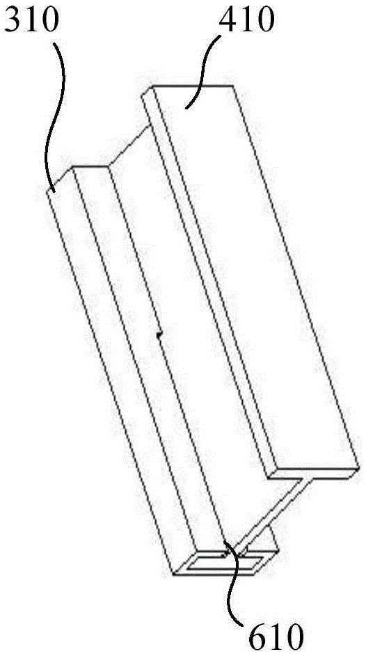
[0047] Method 1: If image 3 with Figure 4 As shown, the first component 310 is a cuboid structure formed by the cooperation of side plates 3103 and 3105 arranged in parallel, side plates 3102, 3104 and side plates 3101 arranged in parallel, wherein side plates 3103, 3102 , side plate 3105 and side plate 3104 are vertically connected successively, and side plate 3103, side plate 3102, side plate 3105 and side plate 3104 are vertically connected with side plate 3101, and there is a slot 510 on the side plate 3103.

[0048] Method 2: If Image 6 with Figure 7 As shown, the first component 320 is a cuboid structure formed by the cooperation of side plates 3201 and 3204 arranged in parallel, side plates 3202 and 3205 arranged in parallel, and side plates 3203, wherein side plates 3201, 3202 , side plate 3204 and side plate 3205 are vertically connected successively, and side plate 3201, side plate 3202, side plate 3204 and side plate 3205 are vertically connected with side pl...


PUM


Abstract

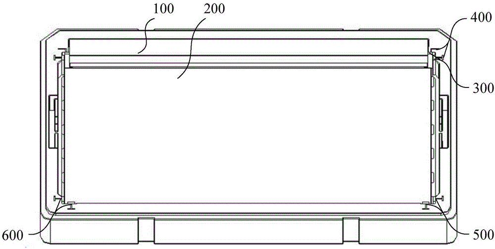
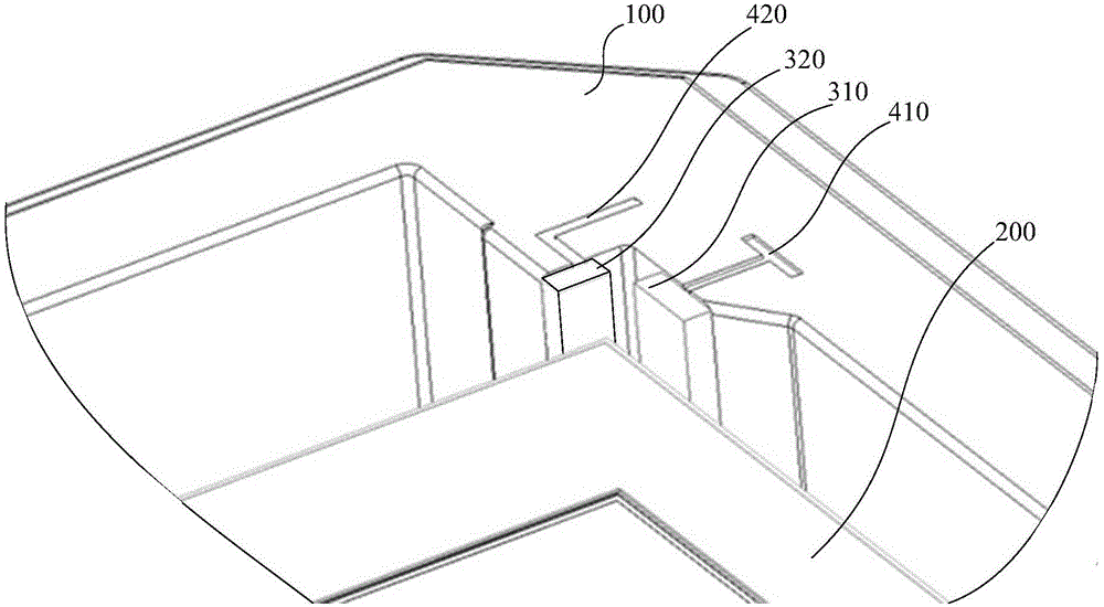
The invention relates to the technical field of cushion packages and discloses a cushion structure used for the inside of a package box and a package structure. The cushion structure used for the inside of the package box comprises a first component and a second component, wherein the second component is matched with the box body of the package box; the first component is prepared from a flexible anti-static material and contacts with a liquid crystal product in the package box; the first component and the second component can be detachably inserted and matched. In the cushion structure used for the inside of the package box, the first component contacting with the liquid crystal product is capable of reducing the generation of static electricity in the package box, the second component is matched with the box body of the package box, so as to exert positioning and cushioning effects; the first and second components can be detachably inserted and matched, and matching stability is high; when one of the first and second components is damaged, the component which is not damaged is combined with other components again. Thus, matching fastness among various parts of the cushion structure in the package box is good, and use cost is low.

Description

technical field [0001] The invention relates to the technical field of cushioning packaging, in particular to a cushioning structure used in a packaging box and a packaging structure. Background technique [0002] In the field of cushioning packaging, the cushioning structure is used for cushioning protection during product movement and handling. For liquid crystal products and electronic products, the cushioning structure needs to have an anti-static function in addition to the cushioning and positioning function. [0003] Most of the existing cushioning structures are separated into one component and packed into a packing box as a whole. In order to realize different functions on one component, most of the cushioning structures on the market currently use two or more components to form one component. [0004] Currently, multiple components of the buffer structure are combined in two ways, such as: [0005] In one way, the components of the buffer structure are bonded by c...

Claims


Application Information

Patent Timeline
IPC IPC(8): B65D81/113B65D85/86
CPCB65D81/107B65D2213/02B65D2585/6837B65D85/68B65D2581/055
Inventor 吕超聂保勇钱志禹张正元李艳平孙勇张骏闫龙陈志远
Owner BOE TECH GRP CO LTD
Learn More