
Automatic conveying type batching shaft bracket

A technology of automatic transportation and cloth reeling, which is applied in the directions of transportation and packaging, winding strips, and thin material processing, etc. It can solve the problems of increasing labor intensity, fabric damage, and waste of human resources, so as to reduce labor intensity and improve Quality, work efficiency improvement effect

Inactive Publication Date: 2015-12-09
SUZHOU XINGYUAN TEXTILE
View PDF9 Cites 2 Cited by
  • Summary
  • Abstract
  • Description
  • Claims
  • Application Information

AI Technical Summary

Problems solved by technology

[0002] In the process of fabric production, the weaving process is an important process in the textile mill. The task of weaving is to interweave the warp and weft yarns that have been dyed and slashed through the loom according to the fabric specifications and according to certain rules. The finished fabric needs to be wound. On the weaving shaft for subsequent inspection, the weaving shaft needs to be transported in a centralized manner during the process of weaving and inspection. The traditional transportation method is to stack the weaving shafts one by one in a development container for centralized transportation. During this process The mutual extrusion and friction of the weaving shafts will cause damage to the fabric, and this process requires the cooperation of two workers, which increases the labor intensity and causes a waste of human resources

Method used


Image

  • Automatic conveying type batching shaft bracket
  • Automatic conveying type batching shaft bracket

Examples


Embodiment

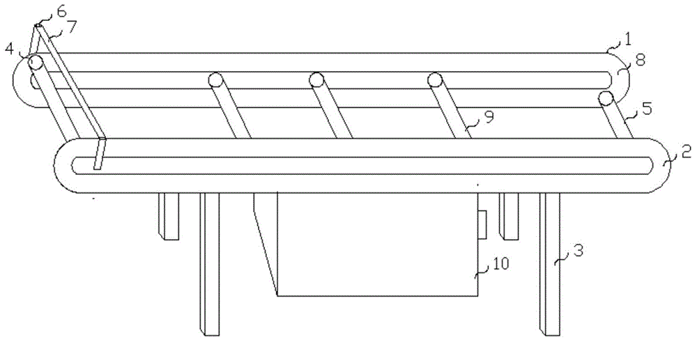
[0015] Example: such as Figure 1-2 As shown, the present invention is an automatic transport reel frame, comprising a first reel frame 1 and a second reel frame 2, the first reel frame 1 and the second reel frame 2 are connected by a number of connecting columns 9, and the bottoms of the first cloth reel frame 1 and the second cloth reel frame 2 are provided with brackets 3, and the first cloth reel frame 1 and the The inner surface of the second cloth winding frame 2 is provided with a slide rail 8, and the slide rail 8 is connected with the first cloth winding shaft 4 and the second cloth winding shaft 5 through a pulley 11, and the first cloth winding shaft 4 and the second cloth winding shaft 5 are connected with the motor 10 through internal lines.

[0016] Two connectors 6 are provided on the outer surfaces of one end of the first cloth roll frame 1 and the second cloth roll frame 2, and the cloth roll inlet shaft 7 is connected through the connectors 6, and the cloth ...


PUM


Abstract

The invention belongs to the field and provides an automatic conveying type batching shaft bracket. The automatic conveying type batching shaft bracket comprises a first batching shaft bracket body and a second batching shaft bracket body which are connected through a plurality of connection columns. The bottoms of the first batching shaft bracket body and the second batching shaft bracket body are both provided with supports. The inner surfaces of the first batching shaft bracket body and the second batching shaft bracket body are both provided with sliding rails. The sliding rails are connected with a first batching shaft and a second batching shaft through sliding wheels. The first batching shaft and the second batching shaft are connected with a motor through an internal circuit. According to the automatic conveying type batching shaft bracket, the motor is utilized to drive the sliding wheels, the functions of automatic batching and automatic conveying are achieved, working efficiency is improved effectively, and labor intensity is lowered; the number of the batching shafts is increased to two, circulation working is achieved, and the working efficiency of the automatic conveying type batching shaft bracket is improved; and meanwhile after batching and conveying are finished, products are separated from the batching shafts through connection buckles, and the next process is carried out.

Description

technical field [0001] The invention relates to a cloth winding device, in particular to a cloth winding shaft frame. Background technique [0002] In the fabric production process, the weaving process is an important process in the textile mill. The task of weaving is to interweave the warp and weft yarns after dyeing and sizing treatment through the loom according to the fabric specifications and according to certain rules. The finished fabric needs to be wound On the weaving shaft for subsequent inspection, the weaving shaft needs to be transported in a centralized manner during the process from weaving to inspection. The traditional transportation method is to stack the weaving shafts one by one in a development container for centralized transportation. During this process The mutual extrusion and friction of the weaving shafts will cause damage to the fabric, and this process requires the cooperation of two workers, which increases the labor intensity and causes a waste...

Claims


Application Information

Patent Timeline
Patent Type & Authority Applications(China)
IPC IPC(8): B65H75/30B65H75/10B65H18/08B65H19/30
Inventor 李斌
Owner SUZHOU XINGYUAN TEXTILE
Learn More