Scribing device
A scribing device and conveyor belt technology, applied in glass cutting devices, transportation and packaging, glass manufacturing equipment, etc., can solve the problems of substrate damage, difficult to maintain the glass neatly arranged, difficult to maintain flat, etc., to achieve accurate lifting position, The effect of preventing misalignment and increasing the interval time
- Summary
- Abstract
- Description
- Claims
- Application Information
AI Technical Summary
Problems solved by technology
Method used
Image

Examples
no. 1 example
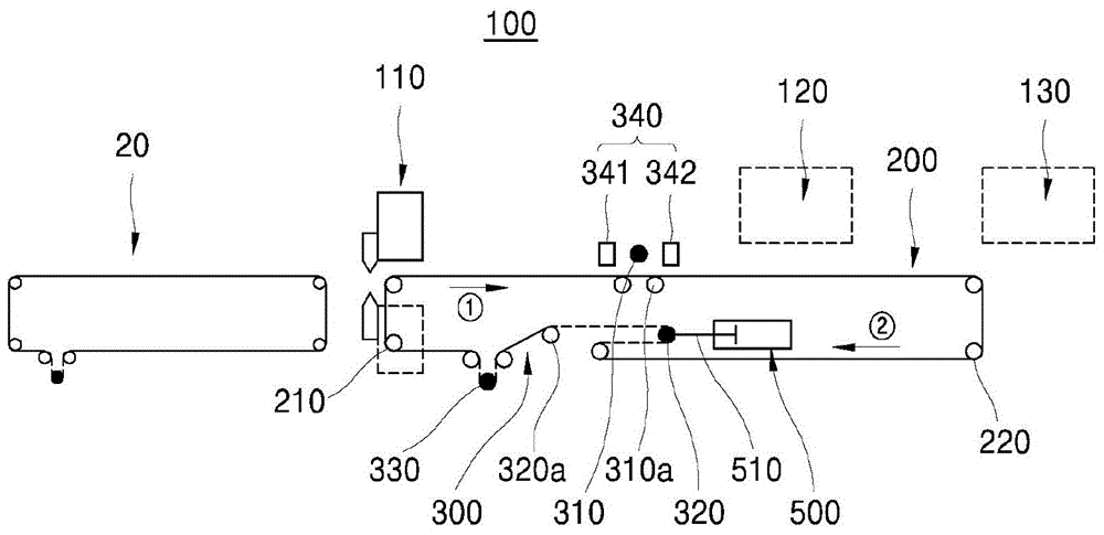
[0058] figure 1 is a schematic diagram showing the scribing device of the present invention
[0059] refer to figure 1 The scribing device of the present invention is roughly composed of a main body 100 provided with a conveyor belt 200 and a process control unit 300 .
[0060] Body 100
[0061] The body 100 according to the invention is provided with a conveyor belt 200 .
[0062] The conveyor belt 200 is disposed on the body 100 so that it can rotate infinitely.
[0063] Both ends of the conveyor belt 200 are rotatably supported by a pair of guide rollers, respectively.
[0064] The above-mentioned pair of guide rolls is composed of the first and second guide rolls 210 on the left side and the first and second guide rolls 220 on the right side.
[0065] The above-mentioned first and second guide rollers 210 on the left side are spaced up and down on the left end of the conveyor belt 200 , so as to rotatably support the left end of the conveyor belt 200 .
[0066] The a...
no. 2 example
[0155] Figure 8 to Figure 12 is a schematic diagram showing another example of the scribing device according to the present invention
[0156] refer to Figure 8 , the first and second self-weight rolls can also be moved by external driving force.
[0157] If the first and second deadweight rolls 310, 320 are forcibly moved along with the expansion and contraction of the shafts 551, 510 of the cylinders 550, 500, the first and second deadweight rolls 310, 320 move independently, while the conveyor belt This position of 200 applies the first and second pressures.
[0158] In particular, the air cylinder 550 for raising and lowering the first deadweight roller 310 along the vertical axis may be installed on the upper portion of the conveyor belt 200 or inside it.
[0159] refer to Figure 9 , the shaft 551 of the air cylinder 550 is connected to both ends of the rotating shaft of the first deadweight roller 310, so that the first deadweight roller 310 can be lifted up and d...
no. 3 example
[0169] In addition, the first and second deadweight rolls according to the present invention can be moved along the vertical axis and can be arranged inside the conveyor belt.
[0170] Figure 13 It is a schematic diagram showing the process of starting the dicing process and the extraction process for the conveyed substrate, Figure 14 It is a schematic diagram showing the process of scribing and picking up the conveyed substrate, Figure 15 is a schematic diagram showing the process of discharging piles, Figure 16 It is a schematic diagram showing the process of transporting the substrate to the extraction process area.
[0171] In describing the substrate transfer apparatus according to the third embodiment, the description of the same configuration as that of the first embodiment will be omitted.
[0172] refer to Figure 13 , the first deadweight roll 310 is disposed inside the upstream conveyor belt 200 and is disposed so as to be movable up and down along a vertica...
PUM
 Abstract
Description
Claims
Application Information
 - R&D
- Intellectual Property
- Life Sciences
- Materials
- Tech Scout
- Unparalleled Data Quality
- Higher Quality Content
- 60% Fewer Hallucinations
Browse by: Latest US Patents, China's latest patents, Technical Efficacy Thesaurus, Application Domain, Technology Topic, Popular Technical Reports.
© 2025 PatSnap. All rights reserved.Legal|Privacy policy|Modern Slavery Act Transparency Statement|Sitemap|About US| Contact US: help@patsnap.com