Well cementation casing or tubing sliding sleeve without limit on number of segments or clusters

A sliding sleeve and well cementing technology, which is applied to wellbore/well components, wellbore/well valve devices, production fluids, etc., can solve the problem of inability to implement drilling and grinding operations, affect production and operation, and fail to meet the multi-stage number of oil and gas wells To meet the needs of fracturing reconstruction and other issues, to achieve the effect of facilitating production and post-operation, reducing the risk of manual operation, and improving the effect of fracturing reconstruction

Active Publication Date: 2015-12-09
PETROCHINA CO LTD
View PDF5 Cites 7 Cited by
  • Summary
  • Abstract
  • Description
  • Claims
  • Application Information

AI Technical Summary

Problems solved by technology

Due to the limitation of the design size of the wellhead, wellbore, construction tubing string and tools, even if the above technologies are continuously optimized and perfected, the diameter of the tubing string decreases step by step during the fracturing process, and the sliding sleeves and ball seats of each section have throttling Affect the construction displacement; and the number of reconstruction sections is limited and the drilling and grinding operations cannot be carried out after the pipe string is n

Method used


Image

  • Well cementation casing or tubing sliding sleeve without limit on number of segments or clusters
  • Well cementation casing or tubing sliding sleeve without limit on number of segments or clusters
  • Well cementation casing or tubing sliding sleeve without limit on number of segments or clusters

Examples


Embodiment 1

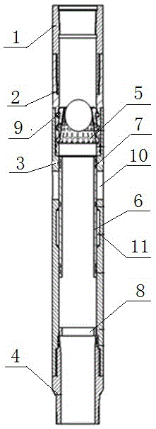
[0026] This embodiment provides a cementing casing or tubing sleeve with unlimited segments and clusters, such as figure 1 As shown, it includes an upper joint 1, a diameter reducing cylinder 2, a sliding sleeve body 3 and a lower joint 4 from top to bottom. The upper inner wall of the sleeve body 3 is threaded, the lower inner wall of the sliding sleeve body 3 is threaded with the upper outer wall of the lower joint 4, and the inner wall of the reducing tube 2 is equidistantly provided with multiple rings of grooves 9 so that the inner wall of the reducing tube 2 forms a concave-convex part There are spaced variable diameter areas, on which an elastic cylinder 5 is installed; the middle of the sliding sleeve body 3 is evenly distributed with a plurality of fracturing ports 10 along the circumferential direction, and the inner wall of the sliding sleeve body 3 is provided with a diameter expanding area 11 , the length of the diameter-expanding area 11 is greater than the lengt...

Embodiment 2

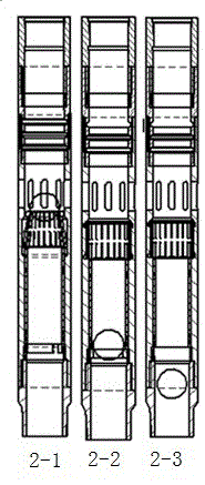
[0032] This embodiment further explains the implementation process of Example 1. During the implementation process, the number of grooves 9 designed on the inner wall of the reducing cylinder 2 depends on the number of sections to be fractured. The first section of the sliding sleeve shall prevail, and one section shall be added. The convex and concave strokes increase by one. The protrusions and grooves of the variable diameter tube in the first section of the sliding sleeve body should be designed according to the length of the elastic tube 5. The design principle is to place the lower end of the elastic tube 5 in the bottommost groove (placed here so that the lower end of the elastic tube is in the expanding position). Diameter state), at this time, the position of the upper end of the elastic cylinder is the position of the corresponding convex groove (it is placed here so that the upper end of the elastic cylinder is in a reduced diameter state). Therefore, in this embodi...

Embodiment 3

[0037] Taking three-stage cementing casing sliding sleeves to fracture a four-section well in layers as an example, the working process of cementing casings or tubing sliding sleeves with unlimited sections is illustrated.

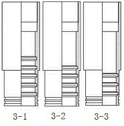
[0038] The present invention connects three-stage cementing casing sliding sleeves according to the number of fracturing layers, and the sliding sleeves are the third sliding sleeve, the second sliding sleeve, and the first sliding sleeve from top to bottom, and the pipe string is lowered to the fracturing layer such as Figure 8 . The third sliding sleeve, the second sliding sleeve, and the first sliding sleeve are designed as follows: Figure 3-1 shown. The initial installation position of the elastic cylinder is as follows from top to bottom: Figure 5-1 , Figure 5-2 , Figure 5-3 , The sliding sleeves are installed with C rings, and balls 1, 2, and 3 are of the same size.

[0039] refer to figure 1 , figure 2 , image 3 , Figure 4 , Figur...


PUM


Abstract

The invention relates to a well cementation casing or tubing sliding sleeve without limit on the number of segments or clusters, comprising an upper joint, a variable-diameter cylinder, a sliding sleeve body, and a lower joint. The upper joint is connected with the variable-diameter cylinder, the variable-diameter cylinder is connected with the sliding sleeve body, and the sliding sleeve body is connected with the lower joint. Grooves are arranged on the inner wall of the variable-diameter cylinder to make a variable-diameter area formed on the inner wall of the variable-diameter cylinder, and an elastic cylinder is installed in the variable-diameter area. Multiple fracturing ports are uniformly distributed in the middle of the sliding sleeve body along the circumference. The inner wall of the sliding sleeve body has a diameter expanding area which is disposed below the fracturing ports. An inner sliding sleeve is arranged inside the sliding sleeve body. The lower end inside the sliding sleeve body is equipped with a C ring. With the sliding sleeve, vertical and horizontal wells in oil and gas fields can be fractured in a layered manner under the conditions of an unlimited number of segments and an unlimited number of clusters between segments. Before fracturing, a wellbore is full-pass, and the sliding sleeve and a ball seat are non-throttled. The construction capacity is larger, the fracturing effect can be significantly improved, and the production capacity of a single well can be increased. After fracturing, a ball made of soluble material and the C ring are dissolved or drilled and ground, and the well bore is full-pass again, thus facilitating later production and operation.

Description

technical field [0001] The invention relates to a cementing casing or oil pipe sliding sleeve with unlimited sections and clusters, which is suitable for the technical field of fracturing reconstruction of vertical wells, inclined wells and horizontal wells in oil and gas fields. Background technique [0002] At present, there are two main types of multi-stage fracturing methods in domestic oil and gas fields: one is to use cable perforation and mechanical packers to achieve isolation between layers, and to complete multi-stage fracturing by sequentially opening fracturing sleeves; It uses hydraulic jet fracturing tools to carry out hydraulic jet perforation, realizes interlayer isolation through hydraulic jet effect, and completes multi-stage reconstruction by jet fracturing. [0003] The above-mentioned sliding sleeves all need to use small to large sealing balls to complete the opening of each section and the isolation from the modified section. Due to the limitation of ...

Claims


Application Information

Patent Timeline
IPC IPC(8): E21B34/06E21B43/26
Inventor 邵媛李宪文张文星张华光任国富任勇郭思文胡开斌蒙鑫冯飞薛晓伟
Owner PETROCHINA CO LTD
Why Eureka
Try Eureka