Mine underground filling system

A technology for mines and pipelines, applied in the field of underground filling systems in mines

Inactive Publication Date: 2015-12-09
王勇
View PDF7 Cites 2 Cited by
  • Summary
  • Abstract
  • Description
  • Claims
  • Application Information

AI Technical Summary

Problems solved by technology

[0008] The beneficial effects of the present invention are: use the filter to dehydrate the water-containing tailings slurry and then send it to the dryer for drying to form dry tailings, and after the dry tailings are stored in the feeding bin, use their own gravity to drop and impact the rotary feeder, Make the rotary feeder rotate at a constant speed to feed the injector, and at the same time, the blower blows air to provide the filling power to blow the dry tailings in the injector to the filling area through the filling pipe, so that the filling work can be carried out without interruption; the filter and dryer function Effectively dehydrate and dry the tailings slurry, which is convenient for blowing in the later stage and improves the conveying efficiency; the rotating mechanism can make the dry tailings from the filling pipe centrifugally move, so that the dry tailings have a wider spreading area, and the outlet of the filling pipe is not easy to block; The whole system is simple in configuration, and has the advantages of low cost and high efficiency; it overcomes the shortcomings of the existing technology that using water conservancy filling requires a large amount of electricity to drain the underground water brought by the tailings slurry and the waiting period after filling, and also overcomes the shortcomings of the existing technology State-of-the-art dry filling utilizes mine trucks or other machinery to transport dry fill material from the ground to fill gobs with inefficiencies

Method used


Image

  • Mine underground filling system

Examples


Embodiment Construction

[0018] The principles and features of the present invention are described below in conjunction with the accompanying drawings, and the examples given are only used to explain the present invention, and are not intended to limit the scope of the present invention.

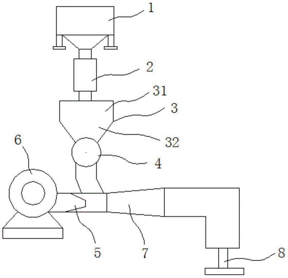
[0019] Such as figure 1 As shown, a mine underground filling system includes a filter 1, a dryer 2, a feed bin 3, a rotary feeder 4, an injector 5, a fan 6, a filling pipeline 7 and a rotary machine 8, and the filter The feed end of 1 is introduced into the tailings slurry through the pipeline, the discharge end of the filter 1 extends into the upper end of the dryer 2, and the lower end of the dryer 2 extends into the feed bin 3, so The lower end of the feed bin 3 communicates with the upper end of the rotary feeder 4, the lower end of the rotary feeder 4 extends into the filling pipeline 7, and the injector 5 is placed in the filling pipeline 7 One side, and the injection port of the injector 5 extends into the f...


PUM


Abstract

The invention relates to a mine underground filling system comprising a filter, a dryer, a feed bin, a rotary feeder, an injector, a fan, a filling pipe, and a rotator. Tailing slurry is introduced into the feed end of the filter through a pipe, and the discharge end of the filter extends into the upper end of the dryer. The lower end of the dryer extends into the feed bin. The lower end of the feed bin is communicated with the upper end of the rotary feeder. The lower end of the rotary feeder extends into the filling pipe. The injector is arranged at one side of the filling pipe, and the injection orifice of the injector extends into a side, at the lower end of the rotary feeder, inside the filling pipe. The fan is arranged at a side, away from the filling pipe, of the injector. The air outlet of the fan is communicated with the air inlet of the injector. The discharge port of the filling pipe is disposed at a side, away from the injection orifice of the injector, of the lower end of the rotary feeder. The rotator is fixedly arranged at the lower end of the discharge port of the filling pipe. By adopting the mine underground filling system, tailings can be dried, the transmission efficiency is high, and the discharge port is not easy to block.

Description

technical field [0001] The invention relates to the technical field of mining machinery, in particular to a mine underground filling system. Background technique [0002] At present, in mining operations, the exploitation of underground resources continuously destroys the balance of the original underground material composition, groundwater flow field, and original rock stress field, and forms an underground goaf. When the mining operation process does not exceed the set control range, the operation process is safe; when the mining operation process is out of control and exceeds the set control range, such as roof fall, water inrush, surface subsidence, debris flow or Mine safety accidents such as surface water influx underground, large-scale ground pressure activities, etc. The occurrence of these safety accidents is closely related to the existence of gobs. If high-quality filling is carried out in the goaf during the mining operation, the above-mentioned safety accident...

Claims


Application Information

Patent Timeline
IPC IPC(8): E21F15/10
CPCE21F15/10
Inventor 王勇
Owner 王勇
Why Eureka
Try Eureka