Plunger pair lubricating and cooling structure for swash plate type plunger pump

A swash plate type plunger pump, lubricating and cooling technology, applied in variable capacity pump components, components of pumping devices for elastic fluid, pump components, etc., can solve the problem of reduced life value of lift pumps and increased gap leakage Increased cooling and heat transfer effects, low agitation heat generation, and enhanced lubrication and cooling

Inactive Publication Date: 2015-12-09
FUZHOU UNIV
View PDF11 Cites 1 Cited by
  • Summary
  • Abstract
  • Description
  • Claims
  • Application Information

AI Technical Summary

Problems solved by technology

[0005] (1) Increasing the gap between the plunger and the cylinder or opening an oil groove on the surface of the plunger increases the leakage of the gap, which reduces the efficiency of the pump to a certain extent, and the high-pressure leakage of the gap will also increase the heat generation of the pump
In addition, the fluidity of the oil in the groove on the surface of the plunger is poor, and the retained oil tends to accumulate heat when the cylinder rotates at high speed. As the temperature of the oil here rises, the lubricating effect will be greatly reduced
[0006] (2) The above design scheme does not involve the influence of the combined effect of the plunger pair’s lubrication enhancement and cylinder cooling, and the temperature control effect meets the bottleneck
In the scheme of only increasing the lubrication of the plunger pair, the local temperature rise caused by the high-speed rotation of the cylinder will significantly reduce the lubrication effect; only considering the cooling of the cylinder body and ignoring the lubrication of the plunger pair, in the face of severe friction and strong friction of the plunger pair caused by lubrication failure. The value of the life of the lift pump with its cylinder cooling is greatly reduced under the temperature rise

Method used


Image

  • Plunger pair lubricating and cooling structure for swash plate type plunger pump
  • Plunger pair lubricating and cooling structure for swash plate type plunger pump
  • Plunger pair lubricating and cooling structure for swash plate type plunger pump

Examples


Embodiment Construction

[0035] The present invention will be further described below in conjunction with the accompanying drawings and specific embodiments.

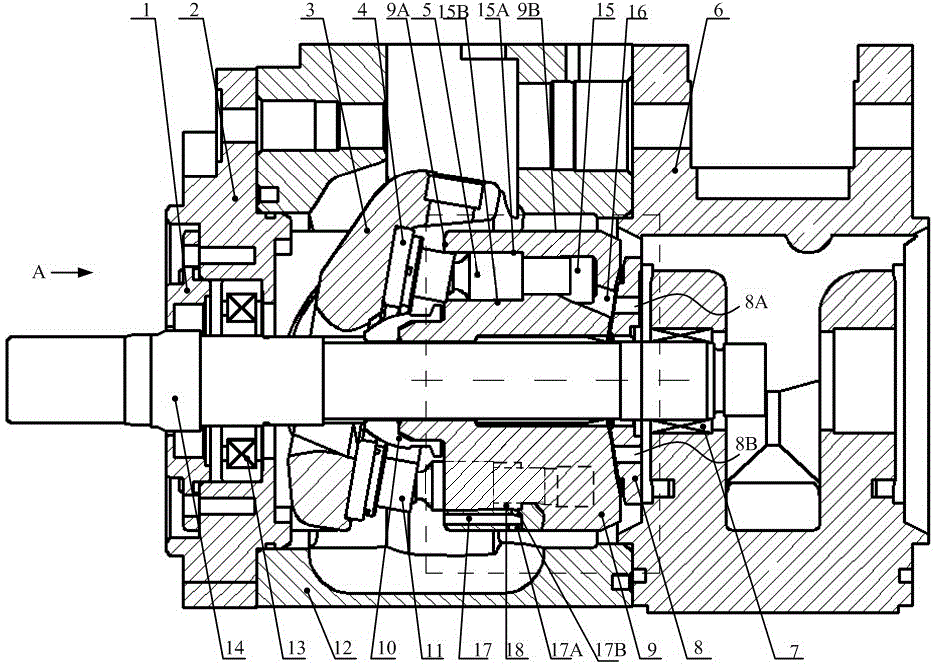
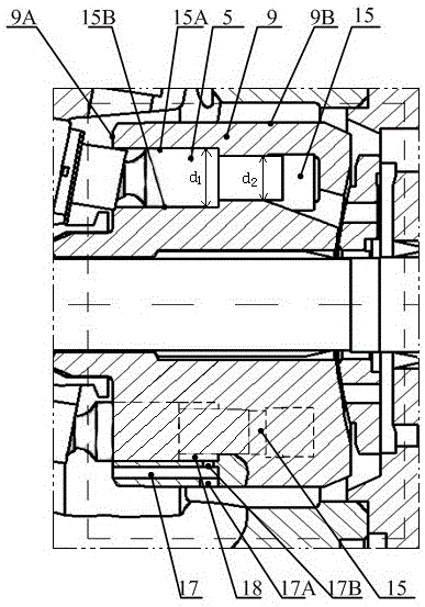
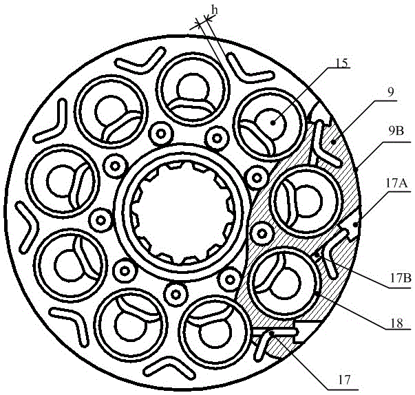
[0036] Such as figure 1 As shown, a plunger pair lubricating and cooling structure of a swash plate type plunger pump includes a cylinder 9 located in the plunger pump body and a plurality of plungers 5, and a number of annular arrays are arranged on the front end of the cylinder 9. The plunger hole 15 is driven by the rotation of the cylinder body 9. The plunger 5 reciprocates and slides in the plunger hole 15 through the swash plate and the sliding shoe; In the hole 15, there is an oil channel system for cooling and lubricating the hole wall. The bottom of the plunger hole 15 is connected with the distribution plate 8 through the waist-shaped hole 16 and communicates with the low-pressure oil suction area 8A and the high-pressure oil discharge area 8B of the flow plate 8. The plunger hole 15 is a stepped cavity with two diameters and the out...


PUM


Abstract

The invention relates to a plunger pair lubricating and cooling structure for a swash plate type plunger pump. A plurality of plunger holes are formed in a cylinder body, an axial cooling oil duct is formed beside each plunger hole in the axial direction of the plunger hole, radial cooling oil ducts are formed in the peripheral surface of the cylinder body in the radial direction of each plunger hole to make the axial cooling oil ducts communicated with the peripheral surface of the cylinder body, the plunger holes and plungers are both of stepped structures, and each stepped structure is composed of two parts with different diameters; when each plunger reciprocates in the corresponding plunger hole, an annular cavity is formed between the plunger which is of the stepped structure and the plunger hole which is of the stepped structure, and the annular cavity is communicated with the corresponding axial cooling oil duct through a plunger pair through-flow oil duct formed in the radial direction of the plunger hole; when the cylinder body rotates at a high speed, the change of the size of each annular cavity enables oil in the corresponding axial cooling oil duct to enter and come out of the annular cavity periodically, and in this way, a plunger pair is lubricated and cooled and the updating rate of oil in the axial cooling oil ducts and cooling effect are improved.

Description

technical field [0001] The invention provides a plunger pair lubricating and cooling structure of a swash plate type plunger pump, in particular relates to a swash plate type plunger pump which is suitable for lubricating and cooling the plunger pair in a high-speed rotation state. Background technique [0002] The swash plate plunger pump is widely used in aerospace, petrochemical, construction machinery and shipbuilding industries due to its advantages of compact structure, high power density ratio, high pressure and high efficiency, and flexible variable mode. At present, with the high-pressure development of axial piston pumps, the heat generated by the three main friction pairs (piston pair, flow distribution pair, and sliding shoe pair) of the swash plate axial piston pump has further increased, and its working heat has accumulated It will increase the friction pair and cause damage such as sticking, which will greatly reduce the service life of the pump. [0003] For...

Claims


Application Information

Patent Timeline
Patent Type & Authority Applications(China)
IPC IPC(8): F04B53/08F04B53/18
Inventor 陈晖梁红星陈嘉阳肖天丽沈明
Owner FUZHOU UNIV
Why Eureka
Try Eureka