Swivel joint

A technology of rotary joints and rotary shafts, which is applied in the direction of pipes/pipe joints/fittings, adjustable connections, turntables/moving tables, etc., which can solve problems such as equipment failures, mechanical wear, and reduce the service life of rotary joints. Strong bearing capacity, long service life and flexible rotation

Active Publication Date: 2015-12-09
CRRC QISHUYAN INSTITUTE CO LTD +1
View PDF4 Cites 7 Cited by
  • Summary
  • Abstract
  • Description
  • Claims
  • Application Information

AI Technical Summary

Problems solved by technology

Due to the large mass of the rail car, in the process of turning around, firstly, it is necessary to overcome the large frictional resistance and the bending moment caused by the deviation of the center of gravity of the rail car; on the other hand, the turning device needs to be turned on the basis of jacking. The strength requirements of the joints are increased, but the existing rotary joints are relatively deficient in flexibility and strength. In addition, manufacturing and assembly errors and vibrations during use may lead to misalignment of the rotary shaft and the rotary sleeve, which will aggravate mechanical wear and reduce Rotary joint service life, causing equipment failure

Method used


Image

  • Swivel joint
  • Swivel joint
  • Swivel joint

Examples


Embodiment 1

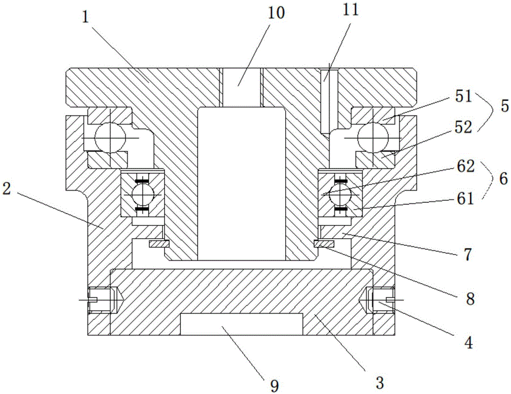
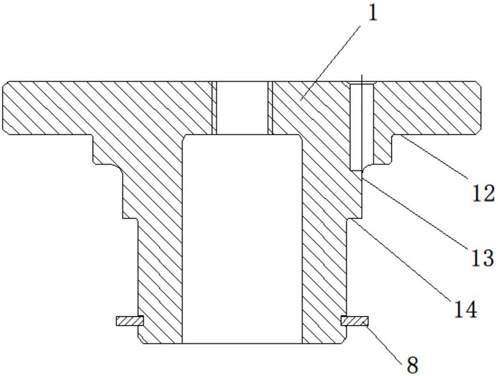
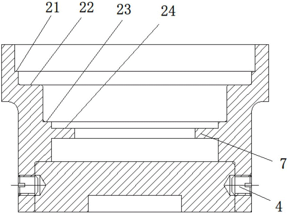
[0042] Such as Figure 1-3 As shown, the present invention provides a rotary joint, including a rotary sleeve 2 and a rotary shaft 1, the lower part of the rotary shaft 1 is sleeved in the rotary sleeve 2, and the lower end of the rotary shaft is rotationally connected with the rotary sleeve 2 A first bearing 5 for providing axial support and a second bearing 6 for providing radial support are arranged between the rotary sleeve 2 and the rotary shaft 1, the raceway 52 of the first bearing is in contact with the The inner hole of the rotary sleeve 2 is matched, the shaft ring 51 of the first bearing is matched with the rotary shaft 1, the outer ring 61 of the second bearing is matched with the inner hole of the rotary sleeve 2, and the The inner ring 62 of the second bearing is sleeved on the rotary shaft 1 . Each component of the rotary joint of the present invention is made of carbon steel or alloy steel, and undergoes quenching and tempering treatment without quenching or n...

Embodiment 2

[0054] Figure 4 It is a schematic structural diagram of the rotary joint of the second embodiment of the present invention, the rotary joint includes a rotary sleeve 2, a rotary shaft 1, a first bearing 5, a second bearing 6 and a top block 3, this embodiment is basically the same as the first embodiment above , the difference is that the thrust ball bearing in Embodiment 1 is replaced by a tapered roller bearing, the seat ring 52 of the thrust ball bearing is replaced by the outer ring 502 of the tapered roller bearing, and the shaft ring 51 of the thrust ball bearing is replaced It is the inner ring 501 of the tapered roller bearing.

[0055] In this embodiment, the tapered roller bearing provides radial support and axial support at the same time, its maximum axial load can reach two tons, and its maximum bending moment can reach 700Nm.

Embodiment 3

[0057] See attached Figure 5-12 , The rotary joint of the present invention is used in a jacking, turning, and turning device, and the jacking, turning, and turning device includes a jacking mechanism and a turning mechanism that cooperate with each other. in:

[0058] The jacking mechanism includes a lower support member 31, a jack 34 and a leg 38. The lower support member 31 is a circular cylinder with at least two pairs of first connecting seats at its lower end, and each pair of first connecting seats is connected to a corresponding leg. 38. Each pair of the first connecting seat includes two first blocking pieces 314 with through holes, and a leg 385 is provided at one end of the leg 38, and a pad 311 for adjusting the height of the leg is arranged on the leg 385, and the leg The other end of 38 has a leg supporting part 381 and a leg connecting part 382 with a through hole; the leg and the first connecting seat are hinged through a first connecting mechanism, and the f...


PUM


Abstract

The invention discloses a swivel joint which comprises a swivel sleeve and a swivel shaft. The lower portion of the swivel shaft is sleeved with the swivel sleeve. The lower end of the swivel shaft is connected with the swivel sleeve in a rotating manner. A first bearing for providing axial supporting and a second bearing for providing radial supporting are arranged between the swivel sleeve and the swivel shaft. A seat ring of the first bearing is matched with an inner hole of the swivel sleeve. A shaft ring of the first bearing is matched with the swivel shaft. An outer ring of the second bearing is matched with the inner hole of the swivel sleeve. The swivel shaft is sleeved with an inner ring of the second bearing. According to the swivel joint, two bearing pieces are arranged between the swivel shaft and the swivel sleeve, one bearing piece provides axial supporting on the swivel shaft, and the other bearing piece provides radial supporting on the swivel shaft; and bending moment brought by unbalance loading can be overcome, flexible rotating is achieved, mechanical wear is lowered, and the service life of products is prolonged.

Description

technical field [0001] The invention relates to a connecting joint in railway engineering equipment, in particular to a swivel joint used in a U-turn device for a subway rail car. Background technique [0002] With the construction of subway lines all over the country, the maintenance work of the lines has been paid more and more attention by various subway companies. In subway tunnels, due to the limitation of space, the boundary requirements of subway lines are more stringent, and the subway tunnels are relatively closed, so many large-scale line maintenance equipment cannot be used in subway tunnels. [0003] With the advancement of battery technology, various electric equipment is used more and more frequently, and the technology is becoming more and more mature. At present, various electric railcars are used more and more frequently in the subway. Electric railcars are different from large vehicles. Large vehicles are generally in the There are cabs at both ends of the...

Claims


Application Information

Patent Timeline
Patent Type & Authority Applications(China)
IPC IPC(8): F16L27/00B61J1/02
CPCB61J1/02F16L27/00
Inventor 王印军郭勐
Owner CRRC QISHUYAN INSTITUTE CO LTD
Why Eureka
Try Eureka