
Large-stroke heavy-load slipway structure

A technology of large stroke and sliding table, which is applied in the field of large stroke and heavy-duty sliding table structure, which can solve the complicated design of the dustproof mechanism of the rack and pinion, increase the labor intensity of production workers, increase the shear force of guide rails and sliders, etc. problems, to achieve the effect of reasonable structural design, compact structure, and reduced shear force

Active Publication Date: 2015-12-09
DONGGUAN LEBAOT ROBOT
View PDF7 Cites 5 Cited by
  • Summary
  • Abstract
  • Description
  • Claims
  • Application Information

AI Technical Summary

Problems solved by technology

However, although these slides can roughly meet the requirements of use, the design is not ingenious, and the load capacity is poor, and the installation positions of the racks and pinions are all on one side of the slide frame, which will not only increase the The shearing force between the guide rail and the slider causes a large loss, which greatly shortens the service life of the equipment, and makes the design of the dust-proof mechanism of the rack and pinion complicated, which increases the cost of the equipment. In addition, the slide table is not equipped with an oil lubrication device. 1. The sliding parts cannot be lubricated in time and effectively. In order to reduce wear and tear, only manual timing oiling can be used, which not only increases the labor intensity of production workers, but also affects production efficiency.

Method used


Image

  • Large-stroke heavy-load slipway structure
  • Large-stroke heavy-load slipway structure
  • Large-stroke heavy-load slipway structure

Examples


Embodiment Construction

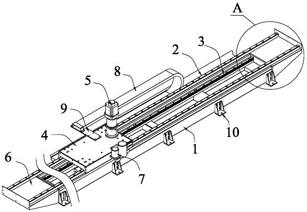
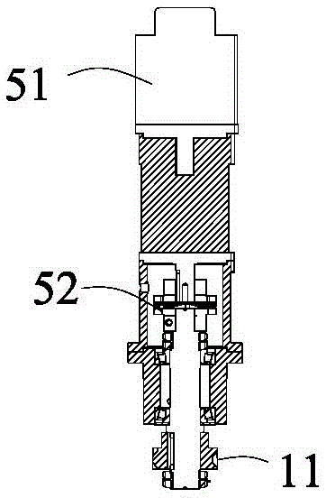
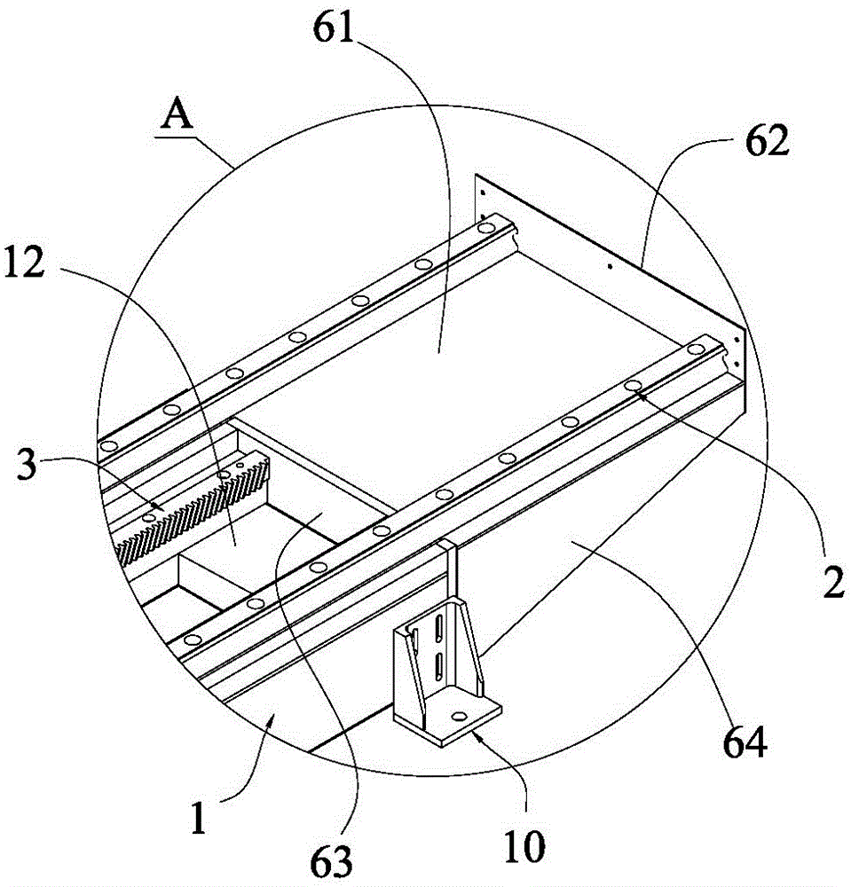
[0016] see figure 1 , figure 2 and image 3 , the present embodiment provides a large-stroke heavy-load sliding table structure, which includes a sliding table frame body 1, a linear sliding rail 2, a transmission rack 3, a load-bearing slide plate 4, a power output device 5, a dust-proof stopper 6 and a supply Oil device 7, two linear slide rails 2 are symmetrically arranged on both sides of the upper surface of the slide frame body 1, the load slide 4 is movably arranged on the linear slide rail 2 through the slide block, the slide frame body 1 There is an accommodating groove 12 extending along the running direction of the linear slide rail 2 at the middle position of the upper surface of the accommodating groove. , the position of the power output device 5 corresponding to the transmission rack 3 is arranged on the load sliding plate 4, and the output end of the power output device 5 is provided with a transmission gear 11 meshing with the transmission rack 3, the suppl...


PUM


Abstract

The invention discloses a large-stroke heavy-load slipway structure which comprises a slipway frame body, linear sliding rails, a transmission rack, a load sliding plate, a power output device, a dustproof blocking piece and an oil supply device. The two linear sliding rails are symmetrically arranged on the two sides of the upper surface of the slipway frame body. The transmission rack is arranged on one side wall of a containing groove. The portion, corresponding to the transmission rack in position, of the power output device is arranged on the load sliding plate. The output end of the power output device is provided with a transmission gear engaged with the transmission rack. The large-stroke heavy-load slipway structure is clever and reasonable in structural design, the transmission rack is located between the two liner sliding rails, the shearing force between a guide rail and a sliding block is lowered effectively, operation stability is good, and site occupation is avoided; the structure is more compact, the occupied area is reduced, and a dustproof structure is simplified greatly; and the oil supply device can supply oil to all movable parts regularly so that a device can operate more flexibly and stably, working efficiency is improved, and wide application and popularization are facilitated.

Description

technical field [0001] The invention relates to the technical field of sliding tables, in particular to a large-stroke heavy-load sliding table structure. Background technique [0002] At this stage, the sliding table has been widely used in the industry. There are a variety of slides on the market, each of which has different design concepts, and strives to meet the requirements of different users. However, although these sliding tables can roughly meet the requirements of use, their design is not ingenious, the load capacity is poor, and the installation positions of their racks and pinions are all on one side of the sliding table frame, which will not only increase the size of the sliding table during operation. The shear force between the guide rail and the slider is large and the loss is large, which greatly shortens the service life of the equipment, and makes the design of the dust-proof mechanism of the rack and pinion complicated, which increases the equipment cost...

Claims


Application Information

Patent Timeline
Patent Type & Authority Applications(China)
IPC IPC(8): F16M11/04F16M11/18F16H19/04F16H57/04H02K7/10
Inventor 卿茂江
Owner DONGGUAN LEBAOT ROBOT
Learn More