Method for measuring vibration using interferometry

A technology of interferometry and interferometer, which is applied in measurement devices, measurement of ultrasonic/sonic/infrasonic waves, and optical devices, etc., and can solve problems such as increased throughput, complex structure, and increased system load.

Active Publication Date: 2015-12-09
SNU PRECISION CO LTD
View PDF4 Cites 1 Cited by
  • Summary
  • Abstract
  • Description
  • Claims
  • Application Information

AI Technical Summary

Problems solved by technology

[0006] In this way, an interferometer for measuring the shape of an object includes a separate oscillatory measurer, and therefore, the entire system has a complex structure
In addition, since the measured oscillation data output from the oscillation measuring device is incompatible with the measured shape data output from the interferometer, the throughput of the system as a whole increases, so the load on the entire system also increases

Method used


Image

  • Method for measuring vibration using interferometry
  • Method for measuring vibration using interferometry
  • Method for measuring vibration using interferometry

Examples


Embodiment Construction

[0017] Hereinafter, an exemplary embodiment of a method of measuring oscillation using interferometry according to the present invention will be described with reference to the accompanying drawings.

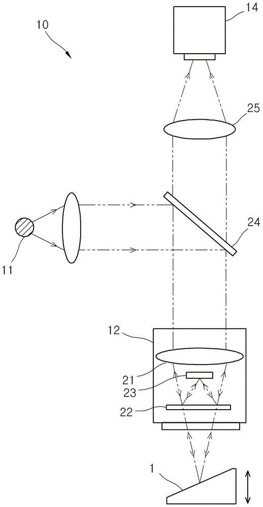
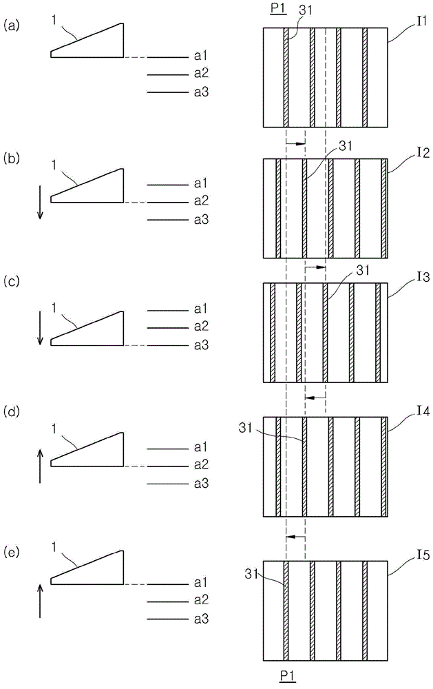
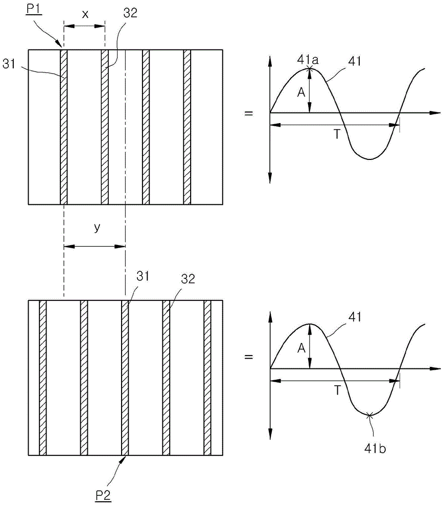
[0018] figure 1 is a view schematically showing interferometry for realizing a method of measuring oscillation using an interferometer according to an embodiment of the present invention; figure 2 is a view showing a step of oscillating an object and obtaining an image of the object in the method of measuring oscillation using an interferometer according to an embodiment of the present invention; and image 3 is a view for explaining a step of calculating an amplitude and a step of calculating a period in a method of measuring oscillation using an interferometer according to an embodiment of the present invention.

[0019] refer to figure 1 , an interferometer 10 for implementing a method for measuring oscillations using an interferometer according to an embodiment of the pre...


PUM


Abstract

The present invention relates to a method for measuring vibration using an interferometer. The method of the present invention comprises: a step for acquiring an image; a step for calculating the movement width; a step for calculating the amplitude; and a step for calculating the cycle. The step for acquiring consecutive image requires an image of the subject to be measured at a certain time interval for the subject to be measured which vibrates with a certain cycle. The step for calculating the movement width calculates the movement width to the left and the right of a moire pattern in the plurality of images acquired. The step for calculating the amplitude calculates the amplitude of the subject to be measured by using the distance between neighboring patterns of the moire pattern, the wavelength of the light irradiated to the subject to be measured, and the movement width to the left and the right of the moire pattern. The step for calculating a cycle calculates the cycle of the subject to be measured by using the time spent by the moire pattern leaving the initial position and returning to the initial position within the movement width to the left and the right of the moire pattern.

Description

technical field [0001] The present invention relates to a method of measuring oscillation using interferometry, and more particularly to a method of measuring oscillation using interferometry in which a property affecting the oscillation of an object is measured using an interferometer. Background technique [0002] An interferometer refers to an instrument that, after emitting light onto the surface of an object to be measured and a reference surface, generates interference fringes caused by reflected or transmitted two beams of light, and measures and analyzes the resulting The above interference fringes are used to obtain information about the surface shape of the object. [0003] Since such an interferometer is easy to measure the shape of an object, it has been widely used in industrial fields. Rapid technological advances throughout industry have recently introduced micromachining into semiconductors, microelectromechanical systems (MEMS), flat panel displays, optical...

Claims


Application Information

Patent Timeline
IPC IPC(8): G01B11/25G01H9/00
CPCG01B9/02001G01H9/00
Inventor 金愍手尹都永朴种宽金兑昱朴喜载
Owner SNU PRECISION CO LTD
Why Eureka
Try Eureka