
A method for measuring the deviation of laser beam from powder cone in laser cladding

A measurement method, laser cladding technology, applied in the direction of measurement devices, metal material coating technology, instruments, etc., can solve the problems of inability to quantitatively reflect the degree of deviation, high risk of visual inspection, long debugging feedback cycle, etc.

Active Publication Date: 2018-01-02
BEIJING HANGTIAN XINFENG MECHANICAL EQUIP
View PDF6 Cites 0 Cited by
  • Summary
  • Abstract
  • Description
  • Claims
  • Application Information

AI Technical Summary

Problems solved by technology

This will greatly affect the cladding process quality
[0006] 2) There is a certain degree of danger: laser processing is strictly forbidden to look directly with the naked eye, and the risk of visual inspection is extremely high
[0007] 3) The debugging feedback cycle is long: visual inspection cannot quantitatively reflect the degree of deviation, and the powder channel needs to be opened after calibration to verify the accuracy of visual inspection by laser cladding

Method used


Image

  • A method for measuring the deviation of laser beam from powder cone in laser cladding
  • A method for measuring the deviation of laser beam from powder cone in laser cladding
  • A method for measuring the deviation of laser beam from powder cone in laser cladding

Examples


Embodiment Construction

[0024] Taking the 316L stainless steel laser cladding test as an example, the specific implementation of the technical plan is as follows:

[0025] 1. Add stainless steel powder;

[0026] 2. Clamp the 5mm thick 316L steel plate on the test bench, and fasten the pressure plate with screws;

[0027] 3. Compile the cladding test program, positive defocus cladding, laser power 700W, travel speed 0.03m / s, head height 12mm; travel path 50mm×50mm (two perpendicular directions), powder feeding volume 10g / min. run the program;

[0028] 4. Cut metallographic: cut cladding parts with grinding wheel in two vertical directions, and polish with sandpaper;

[0029] 5. Smear the corrosion section with passivation paste, observe and measure the deviation degree of the centers of the two samples (corrosion metallography); calculate the deviation degree of the laser beam;

[0030] 6. The deviation calculation method is as follows:

[0031] Let the offsets between the cladding layer and the m...


PUM


Abstract

The invention provides a method for measuring the degree of deviation between the laser beam and the powder cone in laser cladding. The method decomposes the degree of deviation according to two vertical directions, enlarges the observation interval, and adopts the method of cladding the specimen and then cutting and measuring it. Quantitatively calculate the degree of deviation; greatly reduce the error (ΔX>X, ΔY>Y); can directly reflect the amount of laser beam calibration in the later stage; avoid looking directly at the laser, ensuring personal safety.

Description

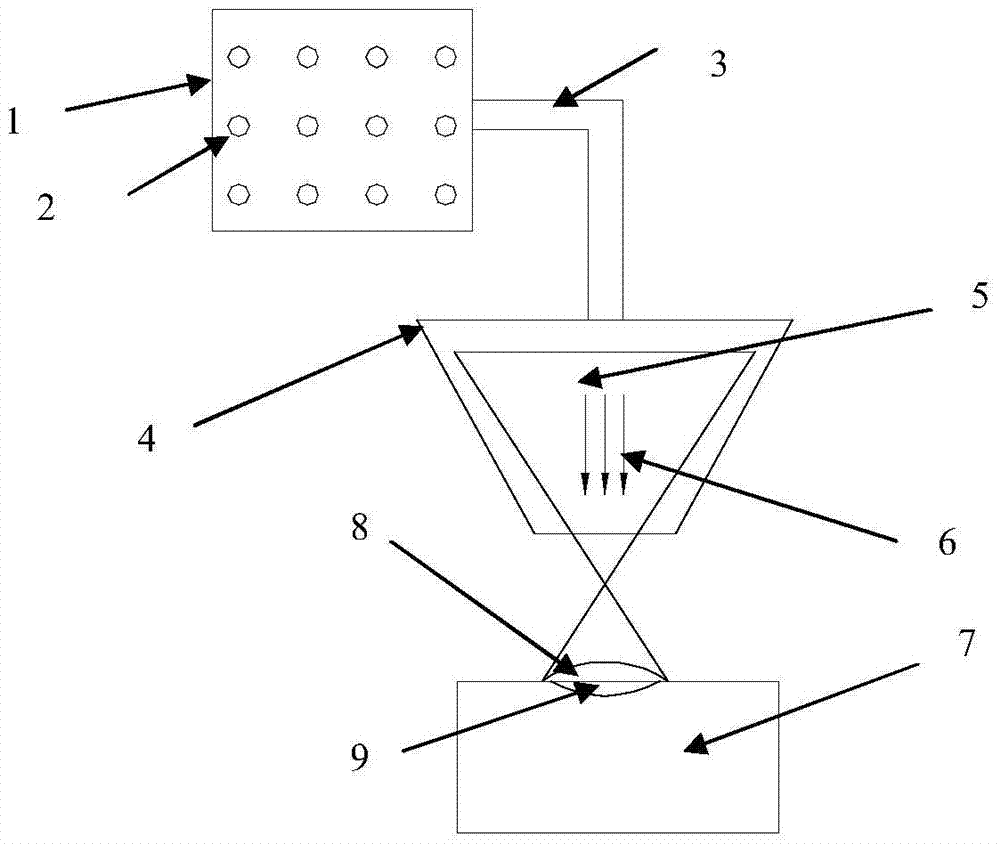
technical field [0001] The invention relates to a method for measuring laser cladding, in particular to a method for measuring the degree of deviation between a laser beam and a powder cone in laser cladding. Background technique [0002] Laser cladding is that the powder 2 in the powder cup 1 passes through the pipe 3 to form a powder cone 5 in the nozzle 4, and uses the coaxial laser beam 6 to melt the powder cone and spray it on the surface of the substrate 7 to form a cladding layer (on the substrate) 8 and the processing method of the molten pool (inside the matrix) 9. Processing principle such as figure 1 shown. [0003] The measurement of the axial deviation between the laser beam and the powder cone is the basis for calibrating the laser beam. Generally, the visual method is adopted, and the specific plan is to close the powder pipeline, turn on the laser beam, paste the photosensitive paper 10 on the nozzle 4, and observe the deviation degree K between the projec...

Claims


Application Information

Patent Timeline
Patent Type & Authority Patents(China)
IPC IPC(8): G01B21/02C23C24/10
Inventor 李昊丞杨雨晨
Owner BEIJING HANGTIAN XINFENG MECHANICAL EQUIP
Learn More