Polarization control-based single mode fiber linear birefringence measuring device and method

A technology of linear birefringence and single-mode fiber, which is applied in measuring devices, material analysis through optical means, instruments, etc., can solve the problem of destroying the linear properties of the system, weakening the suppression effect of linear birefringence, and inability to accurately quantify circular birefringence, etc. question

Active Publication Date: 2015-12-09
CHINA UNIV OF MINING & TECH
View PDF6 Cites 5 Cited by
  • Summary
  • Abstract
  • Description
  • Claims
  • Application Information

AI Technical Summary

Problems solved by technology

[0004] The linear birefringence of single-mode fiber is common in various precision optical sensing systems. For example, the core part of an optical fiber current transformer is a sensitive loop based on a low-birefringence single-mode fiber. The linear birefringence caused by factors such as external temperature fluctuations or vibrations Refraction will not only annihilate useful signals and reduce measurement sensitivity, but also destroy the linearity of the system and reduce measurement accuracy
[0005] At present, the linear birefringence of single-mode fibers can be suppressed by introducing circular birefringence, and circular birefringence can be introduced in a variety of effective ways, including structural helical fibers, twisted low-birefringence fibers, or twisted high-birefringence fibers. However, , the introduced circular birefringence cannot be accurately quantified, which directly weakens the suppression effect on linear birefringence; because the mathematical relationship among precision optical sensing system measurement accuracy, circular birefringence and linear birefringence can often be determined Established, and system measurement accuracy requirements are usually determined in advance, so the basis for accurate quantification of circular birefringence is to achieve accurate measurement of linear birefringence

Method used


Image

  • Polarization control-based single mode fiber linear birefringence measuring device and method
  • Polarization control-based single mode fiber linear birefringence measuring device and method
  • Polarization control-based single mode fiber linear birefringence measuring device and method

Examples


Embodiment Construction

[0041] The present invention will be further described below in conjunction with accompanying drawing.

[0042] Among them, the present invention is attached figure 1 as a basis, with figure 1 The left, right, up, down, center, and focus of the present invention are left, right, up, down, center, and focus. It should be noted that the relative arrangement, numerical values, etc. of components set forth in the present embodiment are not limited to the scope of the present invention unless specifically stated otherwise.

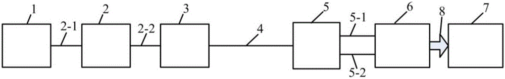
[0043] Such as figure 1 As shown, a single-mode optical fiber linear birefringence measurement device based on polarization control, which includes:

[0044]Broadband light source 1, polarization controller 2, high-speed polarization state analyzer 3, single-mode fiber to be tested 4, polarization beam splitter 5, spectrum analyzer 6, and industrial computer 7;

[0045] The output interface of the broadband light source 1 is connected to the input pigtail 2...


PUM

PropertyMeasurementUnit
lengthaaaaaaaaaa

Abstract

The invention discloses a polarization control-based single mode fiber linear birefringence measuring device. The polarization control-based single mode fiber linear birefringence measuring device comprises a broadband light source, a polarization controller, a high speed polarization state analyzer, a polarization beam splitter, an optical spectrum analyzer, and an industrial personal computer; the output interface of the broadband light source is connected with an input fiber pigtail of the polarization controller; an output fiber pigtail of the polarization controller is connected with the input interface of the high speed polarization state analyzer; the output interface of the high speed polarization state analyzer is connected with a single mode fiber to be tested, and the single mode fiber is also taken as an input fiber pigtail of the polarization beam splitter; an output fiber pigtail of the polarization beam splitter is connected with the optical spectrum analyzer; and the optical spectrum analyzer is connected with the industrial personal computer via RS232 data line. The invention also discloses a measuring method. The polarization control-based single mode fiber linear birefringence measuring device and the measuring method are capable of eliminating influences of an angle between the polarization direction of linearly polarized light and the birefringence main axis of the single mode fiber on linear birefringence measurement, quantizing the angle between the birefringence main axis of the single mode fiber and the polarization principal axis of the polarization beam splitter, and realizing high accuracy measuring of single mode fiber linear birefringence.

Description

technical field [0001] The invention relates to a single-mode optical fiber linear birefringence measurement device and method based on polarization control, and belongs to the technical field of single-mode optical fiber polarization measurement. Background technique [0002] When a beam of linearly polarized light waves propagates in a single-mode fiber, it will be decomposed into two mutually perpendicular polarization modes. Under ideal conditions, these two orthogonal polarization modes have the same propagation constant. In other words, the two orthogonal polarization modes Polarization modes can be degenerate; however, in practical single-mode fibers, the two orthogonal polarization modes generally do not have the same propagation constant, and their combined polarization will vary along the length of the single-mode fiber, forming a single-mode fiber linear birefringence. [0003] The linear birefringence of single-mode fiber can be divided into intrinsic linear bir...

Claims


Application Information

Patent Timeline
Patent Type & Authority Applications(China)
IPC IPC(8): G01N21/23
Inventor 许少毅李威王禹桥邢方方
Owner CHINA UNIV OF MINING & TECH
Why Eureka
Try Eureka