Device and method for laser rangefinder receiving field-of-view calibration and optical axis parallelism measurement

A laser range finder, optical axis parallel technology, applied in the direction of measuring devices, optical devices, radio wave measuring systems, etc., can solve the problems of receiving field of view calibration and testing without relevant documents, so as to avoid errors, save costs, Simple operation effect

Active Publication Date: 2015-12-09
BEIJING RES INST OF SPATIAL MECHANICAL & ELECTRICAL TECH
View PDF3 Cites 26 Cited by
  • Summary
  • Abstract
  • Description
  • Claims
  • Application Information

AI Technical Summary

Problems solved by technology

[0005] Existing testing methods are all testing devices and methods for the matching degree of receiving and receiving optical axes. Different laser rang

Method used


Image

  • Device and method for laser rangefinder receiving field-of-view calibration and optical axis parallelism measurement
  • Device and method for laser rangefinder receiving field-of-view calibration and optical axis parallelism measurement
  • Device and method for laser rangefinder receiving field-of-view calibration and optical axis parallelism measurement

Examples


Embodiment Construction

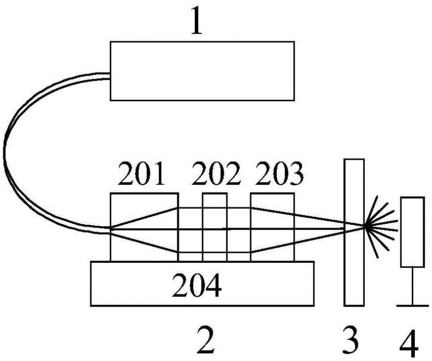
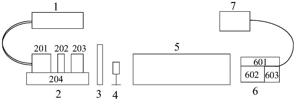
[0037] When the laser ranging system is installed and tested on the ground, it is necessary to measure and calibrate the matching of the optical axis, so that the central field of view of the receiving optical system and the emitting optical axis can be registered with high precision. The measurement method proposed by the present invention is to make the laser light emitted by the emitting laser reflected by the collimator light pipe to make an image point on the focal plane of the light pipe, so as to calibrate the emission optical axis, and then make an analog echo signal source through the auxiliary light source, and change the signal The optical axis of the source is pointed to simulate the echo of different fields of view, and the intensity of different echo signals is simulated by changing the power of the signal source. The angle error Δθ between the optical axis of the echo signal and the emission optical axis is measured by measuring the focal plane of the collimator ...


PUM

PropertyMeasurementUnit
Pulse widthaaaaaaaaaa

Abstract

A device and a method for laser rangefinder receiving field-of-view calibration and optical axis parallelism measurement are provided. The invention relates to a device and method for laser rangefinder receiving center field-of-view calibration and field-of-view measurement. The device comprises a calibration light source, a beam shaping and precision adjusting component, a diffuse transmission plate, a power meter, a collimator, a laser ranging system to be tested, and an oscilloscope. The device and the method of the invention not only can be used to calibrate the field of view of a laser receiving center and measure the range of the receiving field of view, but also can be used to measure the parallelism between a transmitting optical axis and a receiving optical axis. The device and the method are mainly characterized in that calibration of the center field of view of a laser rangefinder, measurement of the field-of-view range and measurement of parallelism between the transmitting and receiving optical axes are realized by using an auxiliary calibration light source with high beam quality to produce simulated echo and scanning the receiving field of view.

Description

technical field [0001] The invention relates to field of view calibration and measurement technology, in particular to a device and method for calibrating a central field of view and accurately measuring a receiving field of view based on an auxiliary light source. Background technique [0002] The space long-distance laser ranging system is mainly used in space-borne laser altimetry, space small target measurement, space rendezvous and docking and other fields. The laser emission angle is usually small, on the order of micro-radians to milliradians. Influenced by the detection sensitivity, the field of view of the receiving system must be as small as possible, and the field of view of the receiving system must be matched with the field of view of the emission with high precision. A small error in the included angle of the optical axis will lead to the reduction of echo energy and the loss of detection probability during long-distance detection. reduce. Therefore, the high-...

Claims


Application Information

Patent Timeline
IPC IPC(8): G01S7/497G01B11/26
CPCG01B11/26G01S7/497
Inventor 许春晓陶宇亮颜凡江穆生博李凌
Owner BEIJING RES INST OF SPATIAL MECHANICAL & ELECTRICAL TECH
Why Eureka
Try Eureka