
Target detection method based on spatial domain phase variance weighting

A technology for target detection and airspace, which is used in measurement devices, re-radiation of sound waves, radio wave measurement systems, etc. It can solve the problems of background noise, large fluctuations in spectral values ​​at azimuth, inconvenience in target detection and azimuth estimation, etc. Gain, improve the signal-to-noise ratio, and suppress the effect of noise interference

Active Publication Date: 2015-12-09
INST OF ACOUSTICS CHINESE ACAD OF SCI
View PDF4 Cites 16 Cited by
  • Summary
  • Abstract
  • Description
  • Claims
  • Application Information

AI Technical Summary

Problems solved by technology

[0006] The purpose of the present invention is to overcome the defect that the target detection method in the prior art is affected by the background noise under the condition of low noise, and the spectral value at each position in the spatial spectrum fluctuates greatly, which is inconvenient for the final target detection and position estimation, thereby providing a A target detection method capable of suppressing noise interference at non-target azimuths and enhancing the signal-to-noise ratio gain of target detection

Method used


Image

  • Target detection method based on spatial domain phase variance weighting
  • Target detection method based on spatial domain phase variance weighting
  • Target detection method based on spatial domain phase variance weighting

Examples


Embodiment Construction

[0041] The present invention will be further described now in conjunction with accompanying drawing.

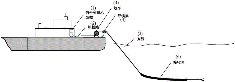
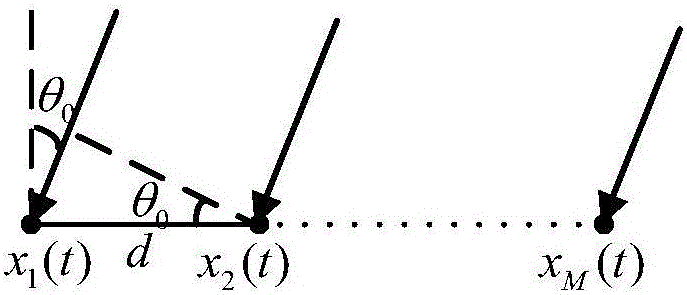
[0042] Before the method of the present invention is described in detail, the receiving array to which the method of the present invention is applicable is firstly described. figure 1 It is a structural schematic diagram of a towing line array sonar, which includes: display and control, signal processor, deck cable, winch, fairlead, towing cable, receiving array; wherein, the deck cable is installed on the winch Above, it is connected to the tow cable through the cable rack; the tow cable is connected to the receiving array; the tow cable is electrically connected to the signal processor and the display control in turn. figure 2 For the receiving signal schematic diagram of the receiving array in the dragging line array sonar, this receiving array is the equidistant horizontal dragging line array (the method of the present invention can be applicable to the array of any form...


PUM


Abstract

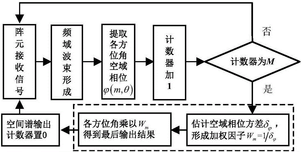
The invention relates to a target detection method based on spatial domain phase variance weighting. The target detection method comprises the steps that filtering and amplification are performed on data picked up by all array elements in a towed line array sonar, and then the picked up data are sampled so that discrete data are obtained; FFT analysis is performed on the discrete data so that frequency spectrum data are obtained; phase compensation, accumulation and summation are performed on the data of all the array elements related to all frequency units in the frequency spectrum data so that frequency domain narrowband wave beam formation is completed; the spatial domain phase value of each azimuth is obtained in the narrowband wave beam formation of all the frequency units; the received signals are updated, the aforementioned operations are performed repeatedly, and each frequency unit obtains multiple spatial domain phase values; variance calculation is performed on the spatial domain phase values of all the azimuths; and weighting factors are generated by variances, and spatial domain phase variance weighting statistics is performed on all the azimuths by utilizing the weighing factors so that the final spatial spectrum and azimuth estimation value can be obtained.

Description

technical field [0001] The invention relates to the field of sonar signal processing, in particular to a target detection method based on space domain phase variance weighting. Background technique [0002] In array signal processing, because passive sonar does not actively radiate signals to the outside, it has strong concealment, and has always been one of the important means to detect, locate, track and identify underwater targets. However, with the continuous improvement of noise reduction technology, the signal-to-noise ratio of passive sonar received data is continuously reduced, and the performance requirements for passive sonar are becoming more and more stringent. The detection technology commonly used in passive sonar—the energy accumulation detection method can no longer meet the needs of long-range target detection. Scholars have proved through theory and experiments that the radiated noise of underwater targets contains rich single-frequency components, especia...

Claims


Application Information

Patent Timeline
IPC IPC(8): G01S15/06
CPCG01S15/06
Inventor 郑恩明陈新华李媛钟茜孙长瑜
Owner INST OF ACOUSTICS CHINESE ACAD OF SCI
Learn More