A narrow pulse fiber laser

A fiber laser and fiber laser technology, applied in the laser field, can solve the problems of lack of narrowing laser pulses, increase signal light repetition frequency, increase system cost, etc., and achieve the effects of reducing costs, increasing single pulse energy, and narrowing pulse width

Inactive Publication Date: 2018-05-18
深圳市欧凌镭射科技有限公司
View PDF6 Cites 0 Cited by
  • Summary
  • Abstract
  • Description
  • Claims
  • Application Information

AI Technical Summary

Problems solved by technology

However, the narrowing of the optical pulse by the gain fiber has certain limitations. For example, in the usual nanosecond MOPA pulsed fiber laser, the optical pulse width of the seed source is generally 200ns. After passing through the fiber amplifier, Optical pulses are usually only narrowed down to tens of nanoseconds
In order to obtain a narrower optical pulse, it is necessary to use a high-speed modulation seed source to obtain a narrow pulse optical signal, which undoubtedly increases the requirements for the seed source; moreover, an input optical signal with a narrow pulse width will result in a lower input signal optical signal. Power, in order to achieve the target optical power, it is necessary to increase the gain of the fiber laser amplifier or increase the number of fiber laser amplifiers, which undoubtedly increases the system cost and reduces the reliability of the system; In the case of , in order to increase the power of the input optical signal, it is necessary to increase the repetition frequency of the signal light, which will lead to a decrease in the energy of the single pulse
Therefore, the prior art still lacks an effective solution for narrowing laser pulses

Method used


Image

  • A narrow pulse fiber laser
  • A narrow pulse fiber laser
  • A narrow pulse fiber laser

Examples


Embodiment Construction

[0009] In order to make the object, technical solution and advantages of the present invention clearer, the present invention will be further described in detail below in conjunction with the accompanying drawings and embodiments. It should be understood that the specific embodiments described here are only used to explain the present invention, not to limit the present invention.

[0010] The specific realization of the present invention is described in detail below in conjunction with specific embodiment:

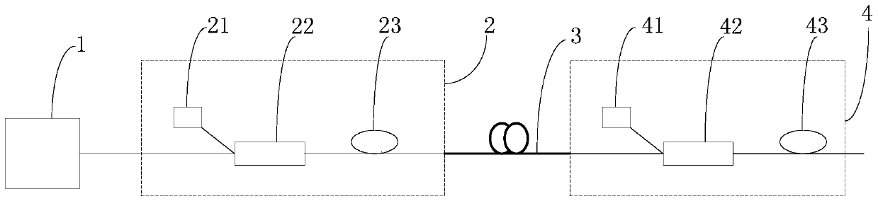
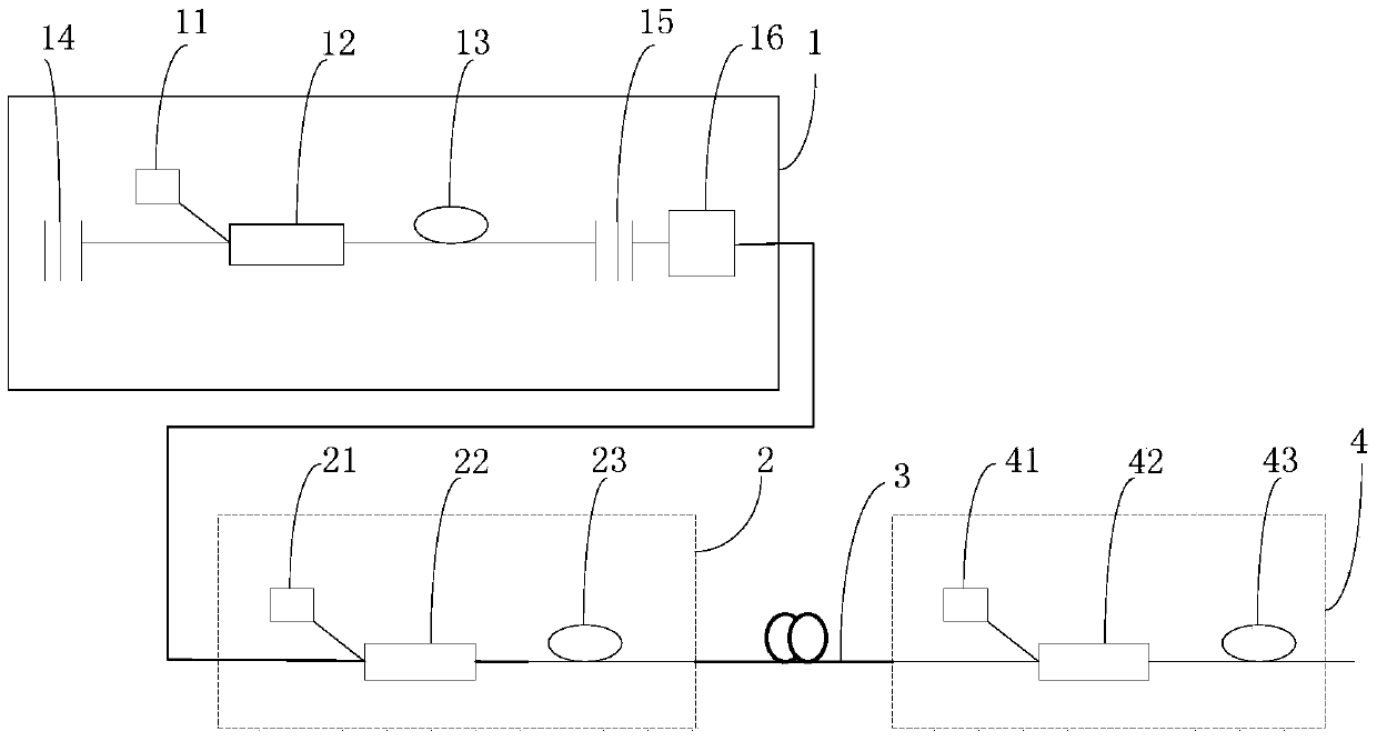
[0011] Please refer to figure 1 , the embodiment of the present invention provides a narrow pulse fiber laser, including a pulse laser transmitter 1 connected in sequence, a pre-stage fiber laser amplifier 2, an optical pulse frequency-shifted narrow line 3 (in an optical fiber structure) and a post-stage fiber laser amplifier 4 , the pulse laser transmitter 1 emits an optical pulse of a certain width, and the optical pulse enters the pre-stage fiber laser amplifier 2, a...


PUM

PropertyMeasurementUnit
poweraaaaaaaaaa
lengthaaaaaaaaaa

Abstract

The present invention is applicable to the field of laser technology, and provides a narrow-pulse fiber laser, which includes a pulse laser transmitter connected in sequence, a front-stage fiber laser amplifier, an optical pulse frequency-shifted narrow line, a rear-stage fiber laser amplifier, and a front-stage fiber laser amplifier. The amplifier amplifies the optical pulse output by the pulsed laser transmitter, and the amplified optical pulse produces nonlinear effects including stimulated Brillouin scattering, Raman scattering, and four-wave mixing in the narrow line of optical pulse frequency shift, so that The energy is collected from the wave front to the tail, and the wavelength is shifted to the long wavelength direction, and the subsequent fiber laser amplifier amplifies the optical pulse to obtain a narrow pulse. The present invention does not need to increase the gain or quantity of the fiber laser amplifier, which reduces the cost and the reliability of the system; it does not need to increase the repetition frequency of the input optical signal, which will not lead to the reduction of single pulse energy; It is a laser that can effectively narrow the pulse width and increase the single pulse energy.

Description

technical field [0001] The invention belongs to the field of laser technology, in particular to a narrow pulse fiber laser. Background technique [0002] Fiber lasers are widely used in industrial fields such as industrial welding, cutting, marking, and engraving, as well as medical, free-space transmission, military, and sensing. Especially in recent years, pulsed fiber lasers have been widely used and promoted. However, the narrowing of the optical pulse by the gain fiber has certain limitations. For example, in the usual nanosecond MOPA pulsed fiber laser, the optical pulse width of the seed source is generally 200ns. After passing through the fiber amplifier, Light pulses are usually only narrowed down to a few tens of nanoseconds. In order to obtain a narrower optical pulse, it is necessary to use a high-speed modulation seed source to obtain a narrow pulse optical signal, which undoubtedly increases the requirements for the seed source; moreover, an input optical sig...

Claims


Application Information

Patent Timeline
Patent Type & Authority Patents(China)
IPC IPC(8): H01S3/067H01S3/30G02F1/35
Inventor 董杰刘一然
Owner 深圳市欧凌镭射科技有限公司
Why Eureka
Try Eureka