
Cable binding seat for sectional bar

A kind of technology of binding seat and profile

Active Publication Date: 2015-12-09
上海天懿自动包装机械有限公司
View PDF11 Cites 7 Cited by
  • Summary
  • Abstract
  • Description
  • Claims
  • Application Information

AI Technical Summary

Problems solved by technology

However, this type of line card is suitable for walls with softer textures, such as walls. For walls made of stainless steel or metal, this line card cannot be used because steel nails are not easy to drive in.
At the same time, the installation and disassembly of this simple line card is also very inconvenient, and it is not easy to disassemble the fixed cable. For this reason, the Chinese invention patent application (publication number CN103591380A) discloses a cable fixer, which has steel nails and movable parts that can be fastened repeatedly. Buckle cable tie, which uses a cable tie that can be buckled repeatedly instead of a fixed-shaped semicircular plastic ring, which is easy to disassemble and can be disassembled and used many times, which solves the problem of disassembly
[0004] However, the above-mentioned structures are all inconvenient to install. For this reason, some electric power and cable companies have made improvements, such as the Chinese invention patent application (notification number CN201674167) discloses a buckle, which has a fixed plastic ring. It has a flat plate with self-adhesive, which is fixed at the selected position with self-adhesive instead of steel nails, easy to install
[0005] However, in the process of pasting and installing the above-mentioned self-adhesives, the applicant found that sometimes it is necessary to adjust the position of the wire buckle. When there are many and heavy, the strength of this sticking method is obviously not enough, and it is easy to fall off, which is a big safety hazard in the electrical control cabinet

Method used


Image

  • Cable binding seat for sectional bar
  • Cable binding seat for sectional bar
  • Cable binding seat for sectional bar

Examples


Embodiment Construction

[0025] In order to further describe in detail the structure and implementation effect of the cable tie seat for profile and the connection member for profile provided by the present invention, the structure of the cable tie seat for profile will be described in detail below.

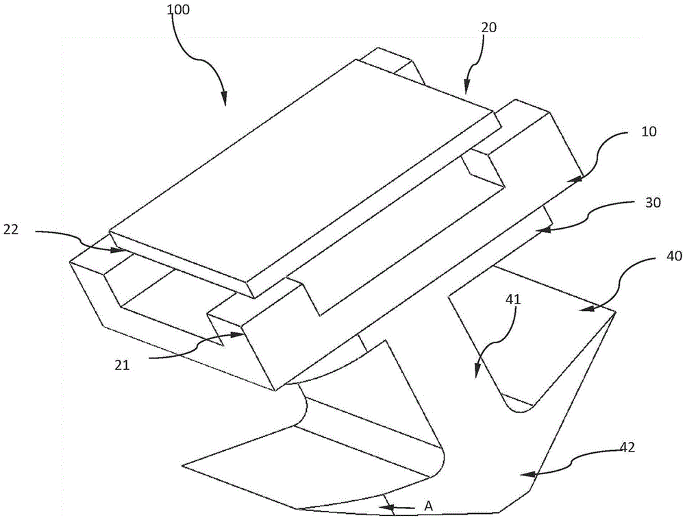
[0026] figure 2 It is a structural schematic diagram of the cable tie seat for profiles in this embodiment

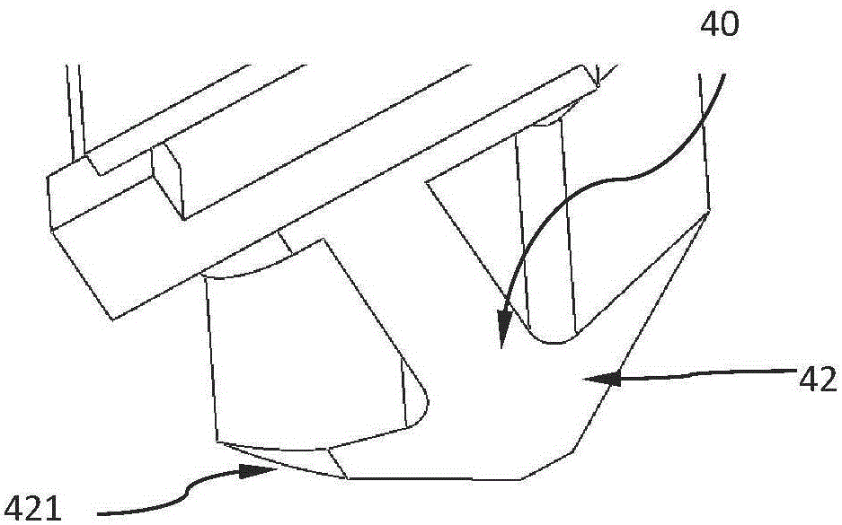
[0027] image 3 for figure 2 Schematic diagram viewed from direction A

[0028] like figure 2 As shown, the cable binding seat 100 for profiles includes: a cover plate 10 , an installation portion 20 , a turntable 30 , and an engaging portion 40 . Wherein, the cover plate 10 is covered on the groove of the profile during use, the mounting part 20 is located on the upper surface of the cover plate 10 and connected with it, the turntable 30 is located on the lower surface of the cover plate 10 and connected with it, and the engaging part 40 is connected with the turntable 30, There are gaps ...


PUM


Abstract

The invention relates to a cable binding seat for a sectional bar. The cable binding seat is used for fixing a cable to a sectional bar component. A groove is formed in the sectional bar; the upper ends of the left side and the right side of the groove are provided with protruding edges which are opposite to each other and form the opening of the groove. The cable binding seat is characterized in that the cable binding seat includes a cover plate which covers the groove of the sectional bar, a mounting part arranged at the upper surface of the cover plate, and a clamping part which is located in the groove; the middle of the mounting part protrudes upwards, so that a through hole can be formed between the mounting part and the cover plate; a binding belt for binding the cable can pass through the through hole; the upper end of the clamping part is connected with the lower surface of the cover plate, so that the cover plate can be clamped into the groove; the clamping part is provided with a connecting unit of which the top end is connected with the lower surface of the cover plate, and two wing sheets which are arranged at the left side and right side of the tail end of a connecting portion with acute angles or right angles formed between the two wing sheets and the connecting unit, so that the top end portions of the two wing sheets can closely contact with the protruding edges of the groove after the clamping part is rotated by a certain angle in the groove.

Description

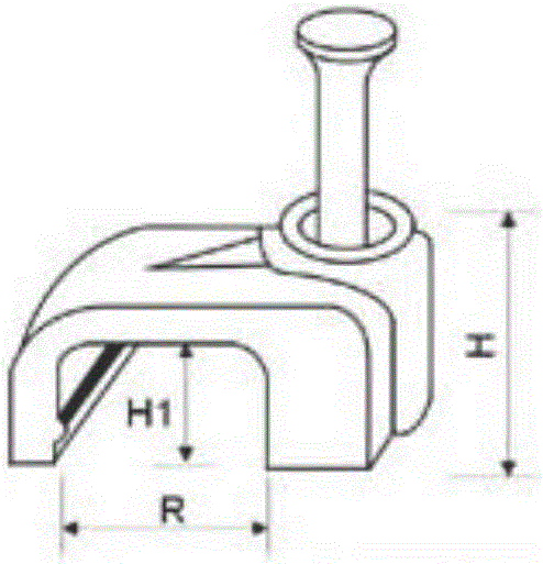
technical field [0001] The invention relates to a cable buckle for profiles, belonging to the field of cable fixers. Background technique [0002] In the electrical cabinets of various packaging machinery with metal profiles as the mechanical skeleton, it is often necessary to lay cables according to the needs of electrical control. From the perspective of safety and space saving, these cables must be bundled and fixed on the profiles. However, after the electrical components are installed, the remaining space in the electrical cabinet is relatively small, and it is difficult to directly bind and fix the cables with cable ties by hand. It is troublesome to bundle and fix cables in the cabinet. [0003] In order to solve this problem, a simple line card has appeared in the prior art, such as figure 1 As shown, the main body of the line card is a semi-circular plastic ring with screws or steel nails on one end of the plastic ring. When using it, first use the plastic ring to...

Claims


Application Information

Patent Timeline
IPC IPC(8): H02G3/02F16L3/04
Inventor 戴龙泉高木康之
Owner 上海天懿自动包装机械有限公司
Learn More