Supercharge Your Innovation With Domain-Expert AI Agents!

Dimmable light-emitting diode (LED) drive circuit

A technology of LED drive and drive circuit, applied in the direction of lamp circuit layout, light source, electric light source, etc., can solve the problems of low energy efficiency, shorten the life of the circuit, etc., achieve the effect of low cost, eliminate power supply waveform distortion, and high efficiency

Inactive Publication Date: 2015-12-09
惠州祺瑞电工有限公司
View PDF3 Cites 1 Cited by
  • Summary
  • Abstract
  • Description
  • Claims
  • Application Information

AI Technical Summary

Problems solved by technology

The technical solution disclosed in CN201510148552 is to connect a resistance heating load in parallel to the light source load as a power dissipation module, and at the same time reduce the power of the light source in the low power area, and maintain the total output power without decreasing by increasing the heating power consumption of the resistance load. This method can obtain a more ideal dimming effect, but the energy efficiency is low, and the high temperature caused by heat will greatly reduce the life of the circuit

Method used


Image

  • Dimmable light-emitting diode (LED) drive circuit
  • Dimmable light-emitting diode (LED) drive circuit
  • Dimmable light-emitting diode (LED) drive circuit

Examples


Embodiment Construction

[0030] In order to enable those skilled in the art to better understand the present invention, the specific implementation manners of the present invention will be further described below in conjunction with the accompanying drawings.

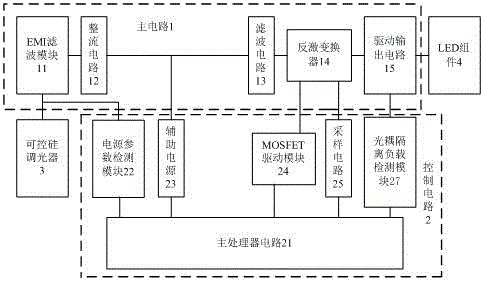
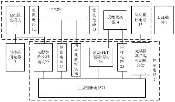
[0031] Such as Figure 4 As shown, the functional block diagram of the dimmable LED driving circuit of the present invention includes a main circuit 1 and a control circuit 2, the main circuit 1 includes, a rectifier circuit 12, and an LED driver module 6; the control circuit 2 includes a main processor circuit 21, a power supply Parameter detection module 22, auxiliary power supply 23; external thyristor dimmer 3 and LED assembly 4 are also marked in the figure.

[0032] Compared with the prior art, the dimmable LED drive circuit provided by the present invention adds a reception control circuit 5, and the power parameter detection module 22 is connected between the output end of the rectification circuit and the main processor circuit to dete...


PUM


Abstract

The invention provides a dimmable light-emitting diode (LED) drive circuit, which comprises a main circuit, a control circuit and a receiving control circuit, wherein the main circuit comprises a rectifying circuit and an LED drive module, which are sequentially connected with each other; the control circuit comprises a power supply parameter detection module, auxiliary power supply and a main processor circuit; the receiving control circuit comprises a switch circuit and a drive circuit; the switch circuit is connected between the rectifying circuit and the LED drive module in series; the drive circuit is connected between the switch circuit and the main processor circuit; and the main processor circuit controls the conduction time duty ratio of the main circuit through the receiving control circuit and further adjusts output of the LED drive module. According to the dimmable LED drive circuit, power supply waveform distortion can be removed; dimming within a low power interval is achieved; and the dimmable LED drive circuit can be widely matched with a silicon-controlled dimming switch in the market at present, and has the advantages of being low in cost, free of rewiring, high in adjustment accuracy, fast in response, high in efficiency, small in size, easy to remotely operate and the like.

Description

technical field [0001] The invention relates to the field of LED drive circuits, in particular to a dimmable LED drive circuit. Background technique [0002] Due to its advantages of high efficiency, energy saving, process and material environmental protection, LED has been rapidly popularized. Because the relationship between LED light emission and current is approximately linear, it is very suitable as a dimming light source. However, if the LED chip used is different, its internal wiring structure and The circuit distribution is different, and its current and voltage parameters are also different. As a result, the light sources of various manufacturers have the same requirements for dimming drive. Therefore, the mismatch between the control system and the light source electrical appliances has become a common problem in the industry. The control system and lighting equipment are not matched, which may cause the lights to go out or flicker, and may cause damage to the LED ...

Claims


Application Information

Patent Timeline
IPC IPC(8): H05B37/02
Inventor 陈涛
Owner 惠州祺瑞电工有限公司
Features
  • R&D
  • Intellectual Property
  • Life Sciences
  • Materials
  • Tech Scout
  • Unparalleled Data Quality
  • Higher Quality Content
  • 60% Fewer Hallucinations
Learn More