Optical coherence scanning imaging device for ophthalmology department
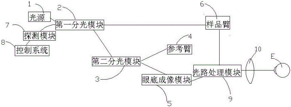
An optical coherent scanning and imaging device technology, which is applied in medical science, ophthalmoscopes, and eye testing equipment, etc., can solve problems such as the difficulty of coating the optical path processing module, and achieve the effects of increasing the difficulty of coating, reducing the difficulty of coating, and saving costs.
- Summary
- Abstract
- Description
- Claims
- Application Information
AI Technical Summary
Problems solved by technology
Method used
Image
Examples
Embodiment 1
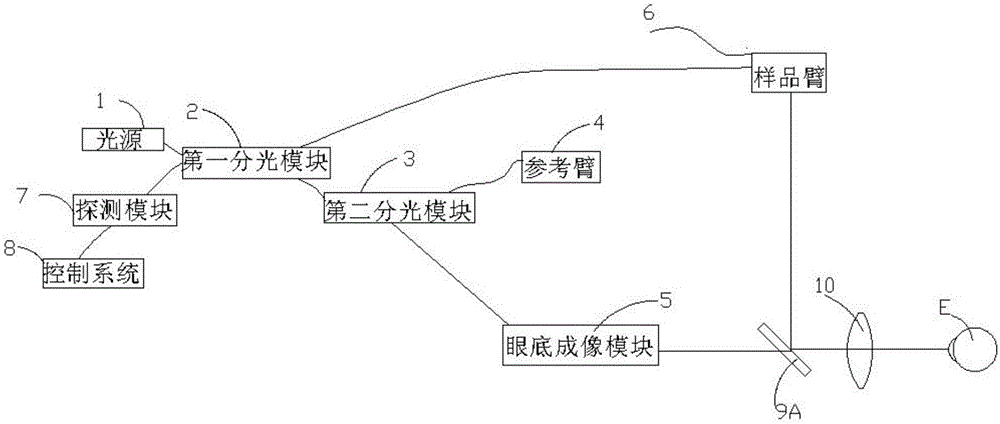
[0034] Example 1: The optical path processing module 9 is a half mirror 9A;
[0035] Please refer to figure 2 After the first light is transmitted to the sample arm 6, the sample arm 6 transmits the received first light to the half mirror 9A, and the first light is reflected to the ophthalmoscope 10 by the half mirror 9A, After passing through the ophthalmoscope 10, it is incident parallel to the human eye. The first light scans the human eye to obtain the fundus signal of the scanned human eye. The half-mirror 9A, the half-mirror 9A reflects it to the scanning module 62 , and transmits it to the first spectroscopic module 2 through the scanning module 62 . The first light carrying the fundus signal interferes with the reference light returning from the reference arm 4 and passing through the second light splitting module 3 at the first light splitting module 2 to form interference light. The interfering light is detected by the detection module 7 and transmitted to the c...
Embodiment 2
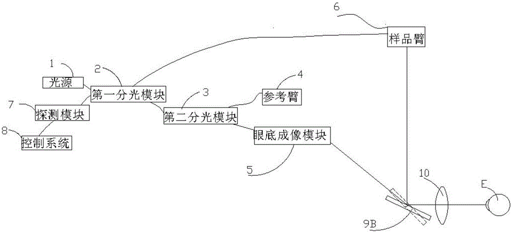
[0038] Example 2: The optical path processing module 9 is a fast switching galvanometer 9B
[0039] refer to image 3 , and Embodiment 1 is different in that the half-mirror 9A in Embodiment 1 is replaced by a fast switching galvanometer 9B. When the fast switching galvanometer 9B is in the position shown by the solid line (namely the first position), imaging of the human fundus can be realized. At this time, the fourth path of light obtained by splitting light from the second spectroscopic module 3 enters the fundus imaging module 5, and the fundus imaging module 5 transmits the fourth path of light to the fast switching galvanometer 9B, and after being reflected by the fast switching galvanometer 9B, the first The four paths of light enter the human eye E through the ophthalmoscope 10 . The fourth light scans the human eye, carries the fundus signal of the scanned human eye, and then scatters through the human eye, returns to the fast switching galvanometer 9B through th...
Embodiment 3
[0042] Example 3: The optical path processing module 9 is a slow switching vibrating mirror 9C
[0043] refer to Figure 4 , and embodiment 2 is different, since the fast switching vibrating mirror 9B in the device is replaced by the slow switching vibrating mirror 9C, so the slow switching vibrating mirror 9C will not switch between the first position and the second position It becomes very frequent, that is, the interval time between the first position and the second position of the vibrating mirror is relatively long, and the specific interval time can be determined according to the switching frequency of the motor. Due to the long interval, the fundus map and OCT map cannot be obtained synchronously.
PUM
 Abstract
Description
Claims
Application Information
 - R&D
- Intellectual Property
- Life Sciences
- Materials
- Tech Scout
- Unparalleled Data Quality
- Higher Quality Content
- 60% Fewer Hallucinations
Browse by: Latest US Patents, China's latest patents, Technical Efficacy Thesaurus, Application Domain, Technology Topic, Popular Technical Reports.
© 2025 PatSnap. All rights reserved.Legal|Privacy policy|Modern Slavery Act Transparency Statement|Sitemap|About US| Contact US: help@patsnap.com


