Secondary optical path focusing structure in receiving module of laser radar ranging system

A technology of ranging system and receiving module, applied in radio wave measurement systems, instruments and other directions, can solve the problems of unstable measurement, high cost, failure of radar ranging, etc., to overcome difficulties in processing and adjustment, compact structure, and easy adjustment. Effect

Active Publication Date: 2012-09-05
FOCTEK PHOTONICS LNC
View PDF1 Cites 0 Cited by
  • Summary
  • Abstract
  • Description
  • Claims
  • Application Information

AI Technical Summary

Problems solved by technology

The optical signal is focused on the optical sensor of the photodetection module through the focusing optical module. Due to machining accuracy and assembly errors, the optical axis of the transmitting module and the optical system of the receiving module are not coaxial, and the position of the optical focus on the optical sensor changes. , exceeding its effective sensing area, resulting in the inability to detect light signals and radar ranging failure
This requires changing the position of the sensor, and adding linear adjustments in the X and Y directions (the plane perpendicular to the optical axis) on the basis of the original Z-

Method used


Image

  • Secondary optical path focusing structure in receiving module of laser radar ranging system
  • Secondary optical path focusing structure in receiving module of laser radar ranging system
  • Secondary optical path focusing structure in receiving module of laser radar ranging system

Examples


Embodiment Construction

[0019] The content of the present invention will be described in detail below in conjunction with the accompanying drawings and specific embodiments:

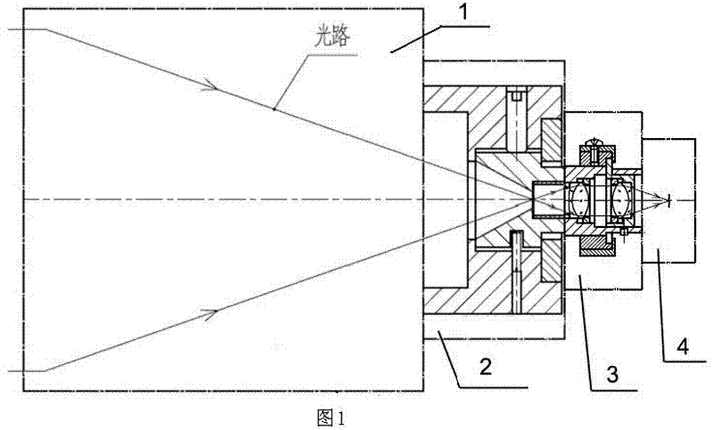
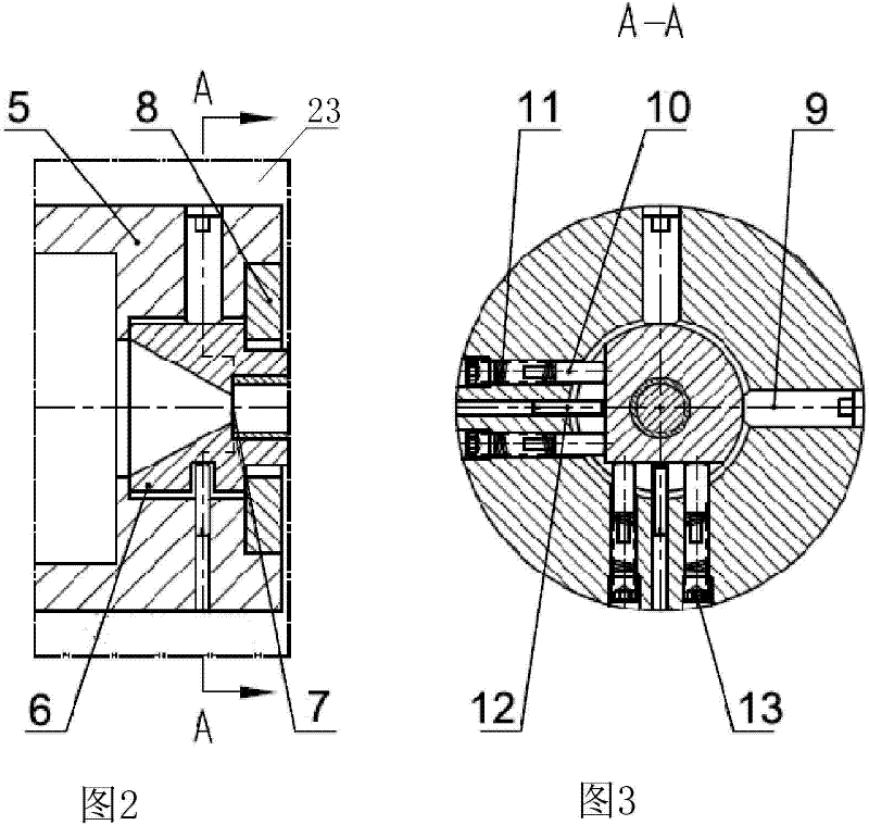
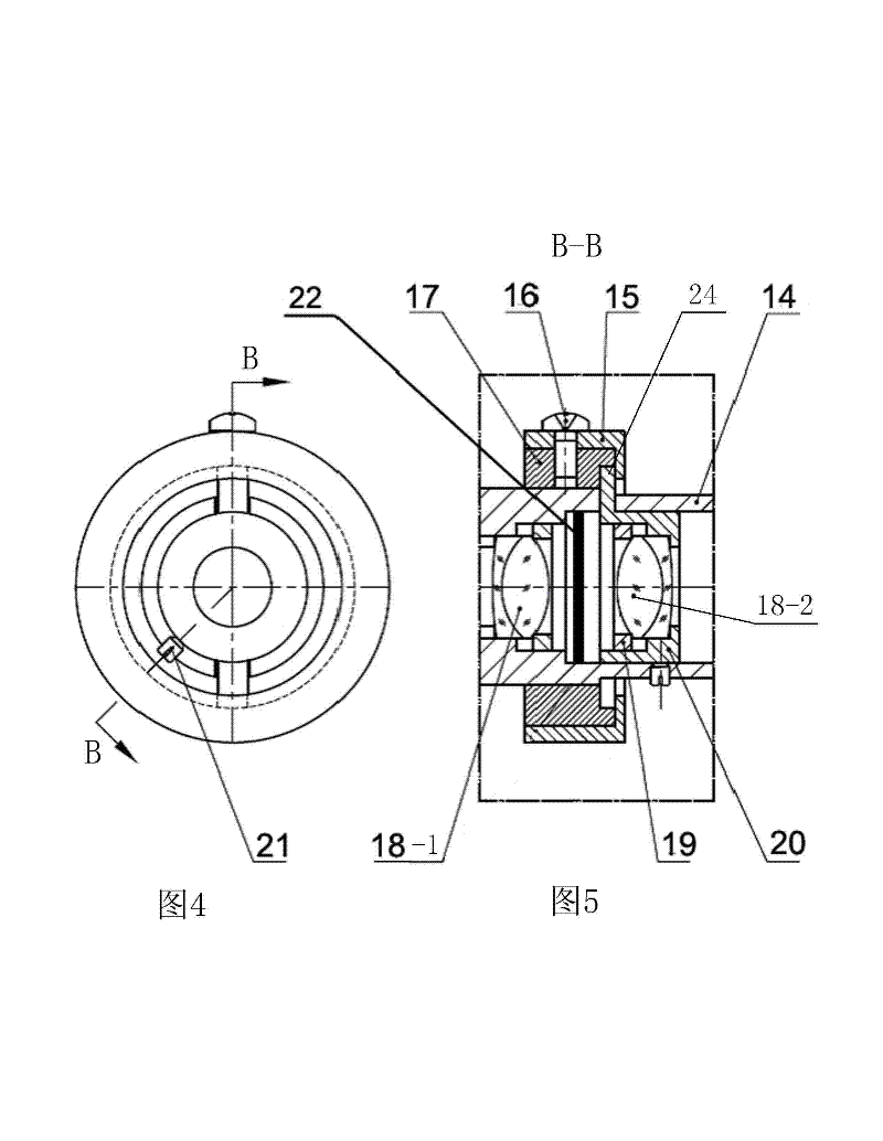
[0020] Such as Figure 1-Figure 5 Shown is the secondary optical path focusing structure in the receiving module of a laser radar ranging system provided by the present invention, which includes a primary focusing optical module 1 and a photoelectric detection module 4, and is characterized in that it also includes a primary focusing optical module The primary focus aperture adjustment module 2 at the focus of 1 and the secondary focus optical module 3 arranged between the primary focus aperture adjustment module 2 and the photodetection module 4; the primary focus aperture adjustment module 2 includes an aperture 7 and a three-dimensional adjustment and fixing mechanism that is used to adjust the XYZ three-way position of the diaphragm 7 on the vertical optical axis and parallel to the optical axis and can fix the diaphragm 7 ...


PUM


Abstract

The invention relates to a secondary optical path focusing structure in a receiving module of a laser radar ranging system, comprising a primary focusing optical module and a photoelectric detection module, further comprising: a primary focusing diaphragm adjustment module and a secondary focusing optical module, wherein the primary focusing diaphragm adjustment module is arranged at a focusing position of the primary focusing optical module and the secondary focusing optical module is arranged between the primary focusing diaphragm adjustment module and the photoelectric detection module; the primary focusing diaphragm adjustment module comprises a diaphragm and a three-dimensional adjusting and fixing mechanism which is used for adjusting the diaphragm at XYZ three-direction positions of a vertical optical axis and a parallel optical axis and fixing the diaphragm on the adjusted position; the secondary focusing optical module comprises a collimation lens group, a converging lens group and a mounting bracket, wherein the collimation lens group is used for collimating the light focused by the primary focusing optical module into parallel light or approximate parallel light; the converging lens group is used for converging the parallel light or approximate parallel light collimated by the collimation lens group to the photoelectric detection module; and the mounting bracket is used for mounting the collimation lens group and the converging lens group. The structure is not only easy for processing, but also simple and convenient for adjusting.

Description

technical field [0001] The invention relates to a laser radar system, in particular to a secondary optical path focusing structure in a receiving module of a laser radar ranging system. Background technique [0002] At present, the working principle of the laser radar ranging system is that the transmitting module transmits a laser signal to the target, and then the receiving module receives the light signal diffusely reflected by the target, and processes the reflected signal to calculate the distance of the target. The receiving module includes a focusing optical module and a photoelectric detection module. The optical signal is focused on the optical sensor of the photoelectric detection module through the focusing optical module. Due to the machining accuracy and assembly error, the optical axis of the transmitting module and the optical axis of the optical system of the receiving module are not coaxial, and the position of the optical focus on the optical sensor changes...

Claims


Application Information

Patent Timeline
IPC IPC(8): G01S7/481
Inventor 陈新锦郭少琴林孝同何金铃黄木旺
Owner FOCTEK PHOTONICS LNC
Why Eureka
Try Eureka