
Double-beam laser alignment system

A laser collimation and double-beam technology, applied in optics, optical components, instruments, etc., can solve the problems of multi-beam laser losing focus, complex optical system, and affecting the repeatability, reliability and accuracy of optical measurement

Pending Publication Date: 2018-10-19
广州光智科技有限公司
View PDF7 Cites 4 Cited by
  • Summary
  • Abstract
  • Description
  • Claims
  • Application Information

AI Technical Summary

Problems solved by technology

Since the exit of the laser is far away from the confocal focus of the multi-beams, factors such as the spot drift of the laser and the mechanical displacement of the optical components in the optical path will cause the multi-beam lasers to lose their confocality, resulting in the weakening or even disappearance of the nonlinear optical signal. This problem is extremely serious. Reduce the performance and stability of optical instruments and equipment, affecting the repeatability, reliability and accuracy of optical measurement
In addition, due to the extremely complex optical systems of nonlinear optical microscopes and time-resolved spectrometers, this problem will greatly affect the convenience and work efficiency of the instruments and equipment, and will greatly increase the workload of users

Method used


Image

  • Double-beam laser alignment system
  • Double-beam laser alignment system

Examples


Embodiment Construction

[0026] In order to make the object, technical solution and advantages of the present invention clearer, the present invention will be further described in detail below in conjunction with the accompanying drawings and specific implementation methods. It should be understood that the specific embodiments described here are only used to explain the present invention, and do not limit the protection scope of the present invention.

[0027] It should be noted that when an element is referred to as being “fixed on”, “disposed on” or “installed on” another element, it may be directly on the other element or there may be an intervening element. When an element is considered to be "connected" to another element, it may be directly connected to the other element or there may be an intervening element at the same time; the specific way that one element is fixedly connected to another element can be realized through existing technologies, and will not be discussed here. To repeat it agai...


PUM

PropertyMeasurementUnit
Angle of incidenceaaaaaaaaaa
Focal lengthaaaaaaaaaa

Abstract

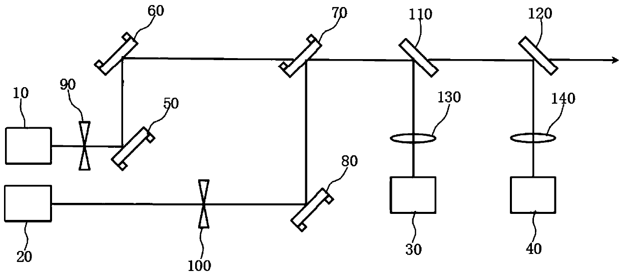
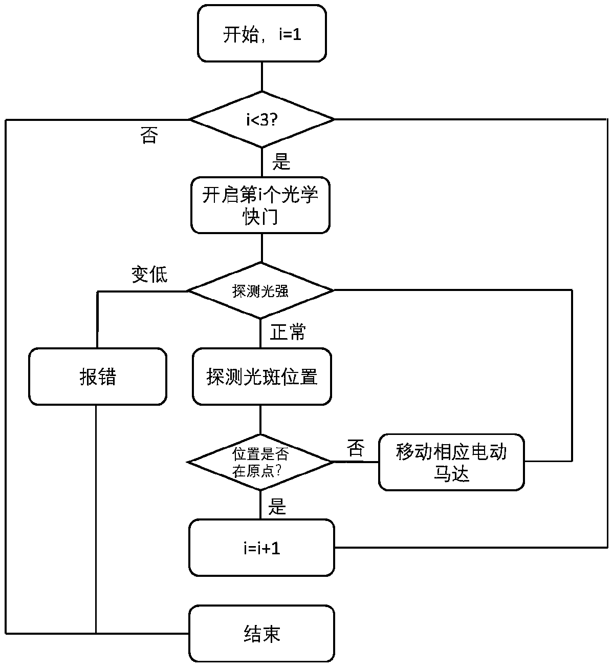
The invention relates to a double-beam laser alignment system. The double-beam laser alignment system comprises a controller, a first incident laser source and a second incident laser source, a firstlaser alignment device and a second laser alignment device, wherein the first incident laser source is provided with a first transmission light path, and the second incident laser source is provided with a second transmission light path; the first laser alignment device comprises a first light path conditioning assembly and a first position sensor which are sequentially distributed in the first transmission light path and both are in electrical control connection with the controller; and the second laser alignment device comprises a second light path conditioning assembly and a second positionsensor which are sequentially distributed in the second transmission light path and both are in electrical control connected with the controller. The system can rapidly achieve light path alignment of two beams of laser in the long-distance transmission, misalignment influences caused by factors such as light spot drift and mechanical displacement of light path optical elements are eliminated, precise collineation of light beams is ensured, and accordingly the using reliability, the stability and the measurement accuracy of an optical instrument are improved.

Description

technical field [0001] The invention relates to the technical field of optical path collimation, in particular to a double-beam laser collimation system. Background technique [0002] At present, nonlinear optical microscopes excited by multi-beam lasers, such as stimulated Raman scattering microscopes, coherent anti-Stokes Raman scattering microscopes, transient absorption microscopes, etc., mainly use titanium sapphire femtosecond lasers with optical parametric oscillators as light sources. The device realizes the confocal of multiple laser beams with different wavelengths, and then generates nonlinear optical signals. Since the exit of the laser is far away from the confocal focus of the multi-beams, factors such as the spot drift of the laser and the mechanical displacement of the optical components in the optical path will cause the multi-beam lasers to lose their confocality, resulting in the weakening or even disappearance of the nonlinear optical signal. This problem...

Claims


Application Information

Patent Timeline
IPC IPC(8): G02B27/30G02B26/08
CPCG02B26/0816G02B27/30
Inventor 朱海蓝栩砚
Owner 广州光智科技有限公司
Learn More