An ophthalmic optical coherent scanning imaging device

An optical coherent scanning and imaging device technology, applied in medical science, fundus mirror, eye testing equipment, etc., can solve problems such as the difficulty of coating the optical path processing module, and achieve the effect of increasing the difficulty of coating, saving costs, and reducing the difficulty of coating.

Active Publication Date: 2016-08-17
SHENZHEN CERTAINN TECH CO LTD
View PDF7 Cites 0 Cited by
  • Summary
  • Abstract
  • Description
  • Claims
  • Application Information

AI Technical Summary

Problems solved by technology

[0003] The present invention provides an ophthalmic optical coherent scanning imaging device, which aims to solve the problems in the optical system caused by using the fundus imaging light source and the OCT imaging light source at the same time in the ophthalmic optical coherent scanning imaging device, and the wavelengths of the light emitted by the two light sources are close. One of the optical path processing modules with transmission and / or reflection functions is difficult to coat

Method used


Image

  • An ophthalmic optical coherent scanning imaging device
  • An ophthalmic optical coherent scanning imaging device
  • An ophthalmic optical coherent scanning imaging device

Examples


Embodiment 1

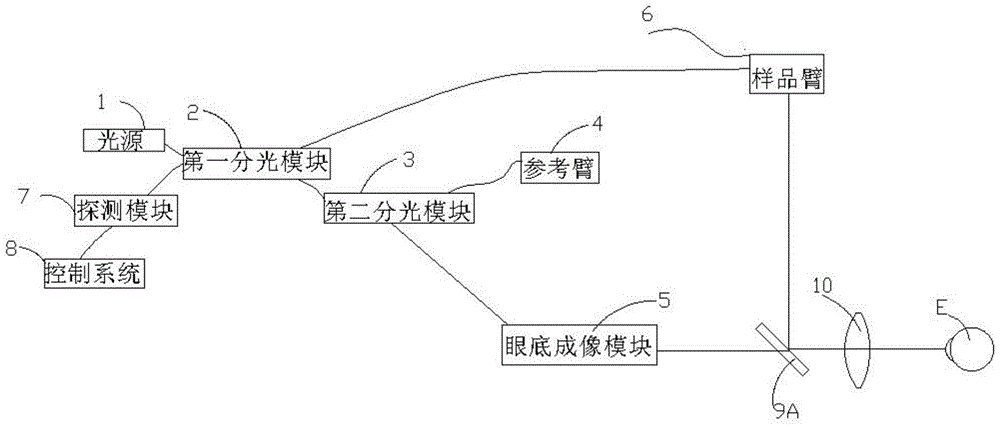
[0034] Example 1: The optical path processing module 9 is a half mirror 9A;

[0035] Please refer to figure 2 After the first light is transmitted to the sample arm 6, the sample arm 6 transmits the received first light to the half mirror 9A, and the first light is reflected to the ophthalmoscope 10 by the half mirror 9A, After passing through the ophthalmoscope 10, it is incident parallel to the human eye. The first light scans the human eye to obtain the fundus signal of the scanned human eye. The half-mirror 9A, the half-mirror 9A reflects it to the scanning module 62 , and transmits it to the first spectroscopic module 2 through the scanning module 62 . The first light carrying the fundus signal interferes with the reference light returning from the reference arm 4 and passing through the second light splitting module 3 at the first light splitting module 2 to form interference light. The interfering light is detected by the detection module 7 and transmitted to the c...

Embodiment 2

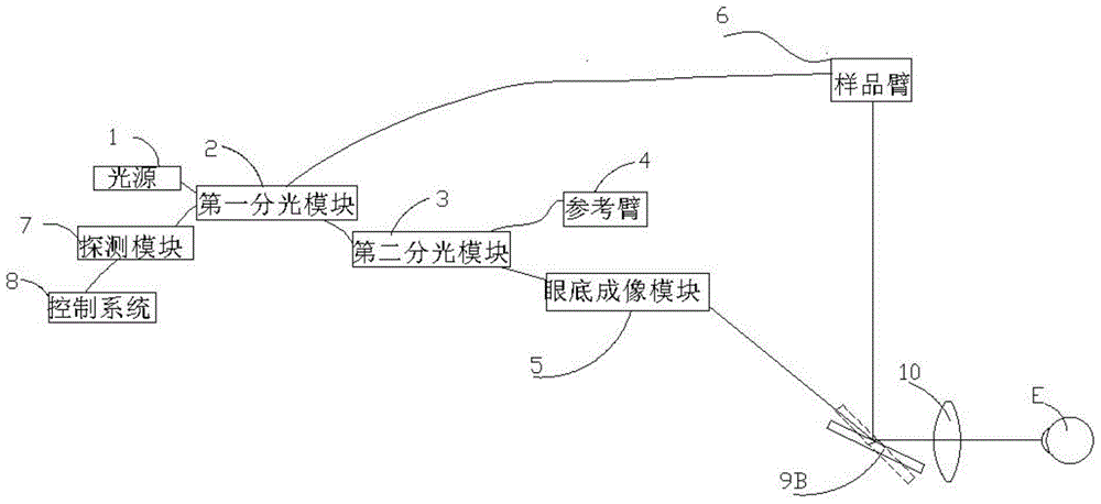
[0038] Example 2: The optical path processing module 9 is a fast switching galvanometer 9B

[0039] refer to image 3 , and Embodiment 1 is different in that the half-mirror 9A in Embodiment 1 is replaced by a fast switching galvanometer 9B. When the fast switching galvanometer 9B is in the position shown by the solid line (namely the first position), imaging of the human fundus can be realized. At this time, the fourth path of light obtained by splitting light from the second spectroscopic module 3 enters the fundus imaging module 5, and the fundus imaging module 5 transmits the fourth path of light to the fast switching galvanometer 9B, and after being reflected by the fast switching galvanometer 9B, the first The four paths of light enter the human eye E through the ophthalmoscope 10 . The fourth light scans the human eye, carries the fundus signal of the scanned human eye, and then scatters through the human eye, returns to the fast switching galvanometer 9B through th...

Embodiment 3

[0042] Example 3: The optical path processing module 9 is a slow switching vibrating mirror 9C

[0043] refer to Figure 4 , and embodiment 2 is different, since the fast switching vibrating mirror 9B in the device is replaced by the slow switching vibrating mirror 9C, so the slow switching vibrating mirror 9C will not switch between the first position and the second position It becomes very frequent, that is, the interval time between the first position and the second position of the vibrating mirror is relatively long, and the specific interval time can be determined according to the switching frequency of the motor. Due to the long interval, the fundus map and OCT map cannot be obtained synchronously.


PUM


Abstract

The invention discloses an optical coherence scanning imaging device for the ophthalmology department. The device comprises a light source, a first beam splitting module, a second beam splitting module, a reference arm, a fundus imaging module, a light path processing module, an ophthalmoscope, a detection module and a control system, wherein light emitted by the light source is divided into four paths, the first light path penetrates through the reference arm, the light path processing module and the ophthalmoscope, comes into human eyes with a fundus signal, and performs interference with the third light path returned from the reference arm in the first beam split module to form an interference light; the detection module is used for receiving the interference light and transmitting the interference light to the control system, and the interference light is processed by the control system to obtain an OCT (optical coherence tomography) graph; the fourth light path sequentially penetrates through the fundus imaging module, the light path processing module and the ophthalmoscope, comes into human eyes with the fundus signal, is returned to the fundus imaging module in the same way, and is processed by the fundus imaging module to obtain a fundus image. According to the device, an OCT light path and a fundus imaging light path can be simultaneously fulfilled by only one light source, and the problem of light path processing module coating difficulty because the OCT light source and the fundus imaging light source having close wavelengths are required can be solved.

Description

technical field [0001] The invention belongs to the field of optoelectronic technology, and in particular relates to an ophthalmic optical coherent scanning imaging device. Background technique [0002] In the existing ophthalmic optical coherent scanning imaging device, the system combining the fundus imaging optical path and the OCT optical path is realized by two sets of light sources and two independent optical path systems, that is, the fundus imaging light source is matched with the fundus imaging optical path system, and the OCT light source is matched with OCT Optical system. Since a system includes both the fundus imaging light source and the OCT light source, and since the wavelength of the light emitted by the fundus imaging light source is close to the wavelength of the light emitted by the OCT light source, if the light splitting elements in the optical path meet the requirements for the light emitted by the imaging light source And the transmission and / or refl...

Claims


Application Information

Patent Timeline
Patent Type & Authority Patents(China)
IPC IPC(8): A61B3/12A61B3/14
Inventor 朱晓湘李鹏王辉郭曙光
Owner SHENZHEN CERTAINN TECH CO LTD
Why Eureka
Try Eureka