
Grinding and polishing device for automatic grinding and polishing machine

A polishing device and polishing machine technology, used in grinding devices, grinding machine tools, preparation of samples for testing, etc., can solve the problems of low polishing efficiency of hard samples, uneven polishing surfaces of samples, and large differences in size, etc., to avoid The effect of uneven polishing surface, improving efficiency, ensuring grinding accuracy and processing efficiency

Active Publication Date: 2015-12-16
HOHAI UNIV
View PDF5 Cites 4 Cited by
  • Summary
  • Abstract
  • Description
  • Claims
  • Application Information

AI Technical Summary

Problems solved by technology

[0004] Technical problem: In order to solve the problem that the existing automatic grinding machine wears the polishing disc because the repairing ring is too heavy when grinding and polishing, the problem that the efficiency is too low when grinding and polishing hard samples, and the sample loading disc and the repairing ring When grinding and polishing a small sample with a small diameter, the sample’s polishing surface is uneven due to the large difference between the size of the sample and the size of the sample carrier. The invention provides a grinding and polishing device for an automatic grinding and polishing machine, which can be used for grinding Polish a single small sample or grind and polish multiple small samples at the same time, and ensure the grinding accuracy

Method used


Image

  • Grinding and polishing device for automatic grinding and polishing machine
  • Grinding and polishing device for automatic grinding and polishing machine
  • Grinding and polishing device for automatic grinding and polishing machine

Examples


Embodiment Construction

[0026] The technical solutions of the present invention will be further specifically described below through specific embodiments and in conjunction with the accompanying drawings.

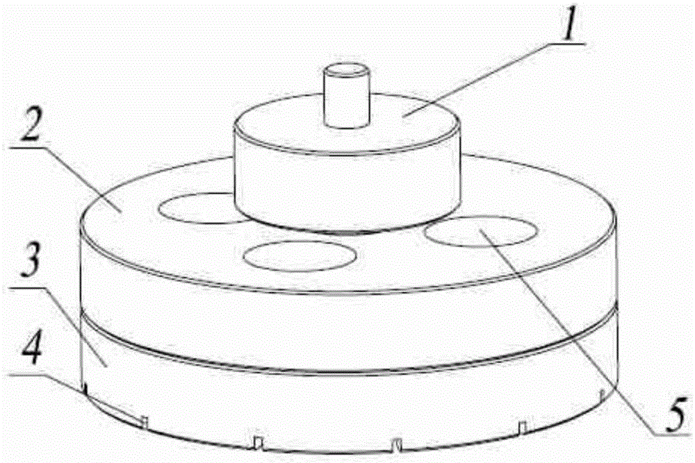
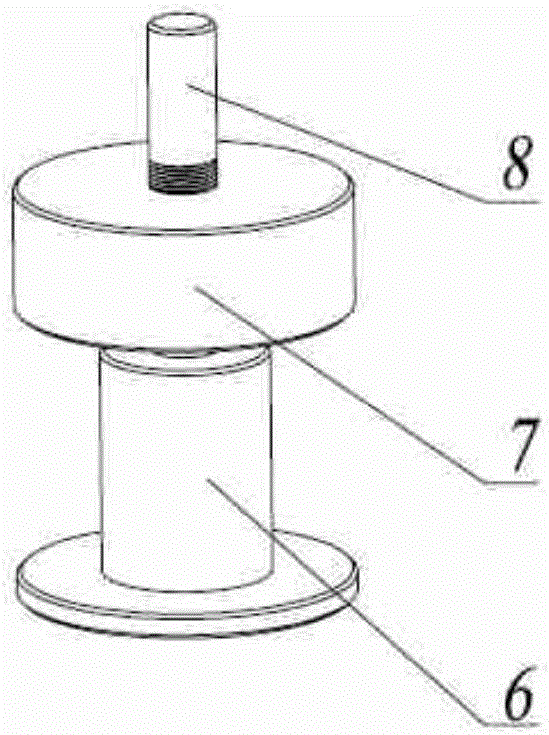
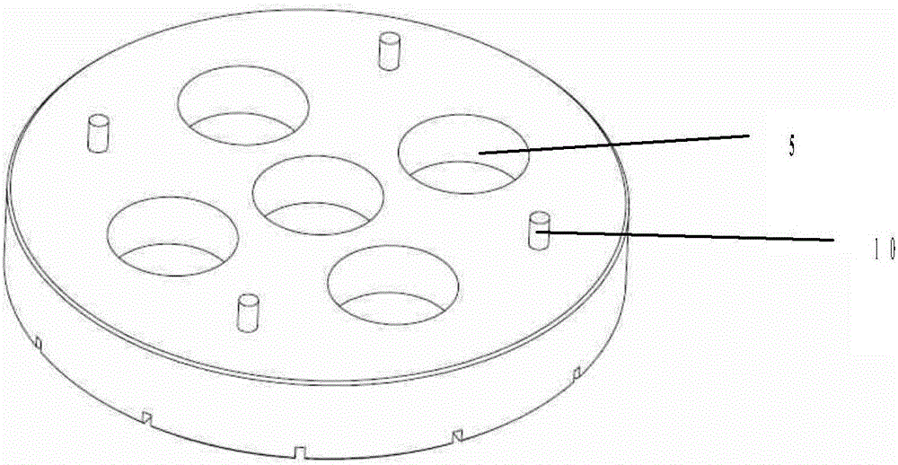
[0027] The invention proposes a grinding and polishing device for an automatic grinding and polishing machine, such as figure 1 As shown, it includes a sample loading tray 1 and a repairing ring, and the repairing ring is a separate structure, including an upper layer repairing ring 2 (such as Figure 4 Shown) and the lower repair disk ring 3 (such as image 3 As shown), wherein, the bottom of the upper sample loading tray is provided with 4 limit grooves 9, the upper surface of the lower sample loading tray is provided with 4 fixed columns 10 corresponding to the limit grooves of the upper sample loading tray, and the upper layer of the sample loading tray is repaired. The ring 2 and the lower repairing ring 3 are fixed through the mutual cooperation of the limiting groove and the fixing post. ...


PUM


Abstract

The invention discloses a grinding and polishing device for an automatic grinding and polishing machine. The grinding and polishing device comprises a disk trimming ring and a sample carrying disk. The disk trimming ring is of an up-down separating type structure, and the weight of an upper disk trimming ring body is smaller than that of a lower disk trimming ring body. A plurality of fixing holes are formed in the surface of the disk trimming ring. The fixing holes are distributed in the surface of the disk trimming ring in a central symmetry mode, or one of the fixing holes is formed in the center of the disk trimming ring and the remaining fixing holes are distributed in a central symmetry mode. A groove with the external diameter being smaller than that of the bottom of the disk trimming ring is formed in the bottom of the lower disk trimming ring body. A plurality of liquid drainage grooves are formed around the bottom of the disk trimming ring. The sample carrying disk and the fixing holes of the disk trimming ring are kept in clearance fit. By the adoption of the grinding and polishing device, a plurality of small samples can be ground and polished at the same time, so that efficiency is greatly improved, and the phenomenon that the polished surface is uneven due to abrasion of tooth blades of the disk trimming ring and lateral skewing of the samples is avoided. Meanwhile, when the samples with high hardness are ground and polished, grinding efficiency and quality can be improved by using a weight increasing body.

Description

technical field [0001] The invention relates to the field of mechanical equipment processing, in particular to a grinding and polishing device for an automatic grinding and polishing machine. Background technique [0002] In order to observe and study the relationship between the composition, structure and performance of some materials, metallographic analysis is required. The invention of the automatic grinding and polishing machine replaces the original manual polishing. It can mechanically and automatically grind and polish the samples to prepare conditions for metallographic analysis, which not only saves time but also improves work efficiency. The automatic grinding and polishing machine is mainly used for grinding and polishing the surface of the workpiece, and is often used in professional fields such as machinery, metallurgy and inorganic non-metals. [0003] The existing automatic grinding and polishing machine includes multiple parts such as a grinding and polishi...

Claims


Application Information

Patent Timeline
Patent Type & Authority Applications(China)
IPC IPC(8): B24B37/27B24B37/34G01N1/32
CPCB24B37/27B24B37/34G01N1/32
Inventor 张建峰李柏涛李改叶吴玉萍杨笑言张欣
Owner HOHAI UNIV
Learn More