Self-driven roadside-parking aid device

A technology of on-street parking and auxiliary devices, which is applied in the field of transportation, can solve problems such as traffic congestion and difficulty in parking small vehicles on the roadside, and achieve the effects of improved functions, huge social benefits and economic value, and convenient operation

Inactive Publication Date: 2015-12-16
肖玉生
View PDF5 Cites 3 Cited by
  • Summary
  • Abstract
  • Description
  • Claims
  • Application Information

AI Technical Summary

Problems solved by technology

[0004] In order to solve the problem of traffic congestion caused by the difficulty of roadside parking for existing small vehicles, the present invention further proposes a self-driven roadside parking auxiliary device

Method used


Image

  • Self-driven roadside-parking aid device
  • Self-driven roadside-parking aid device
  • Self-driven roadside-parking aid device

Examples


specific Embodiment approach 1

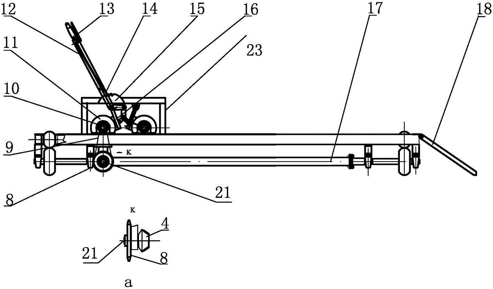
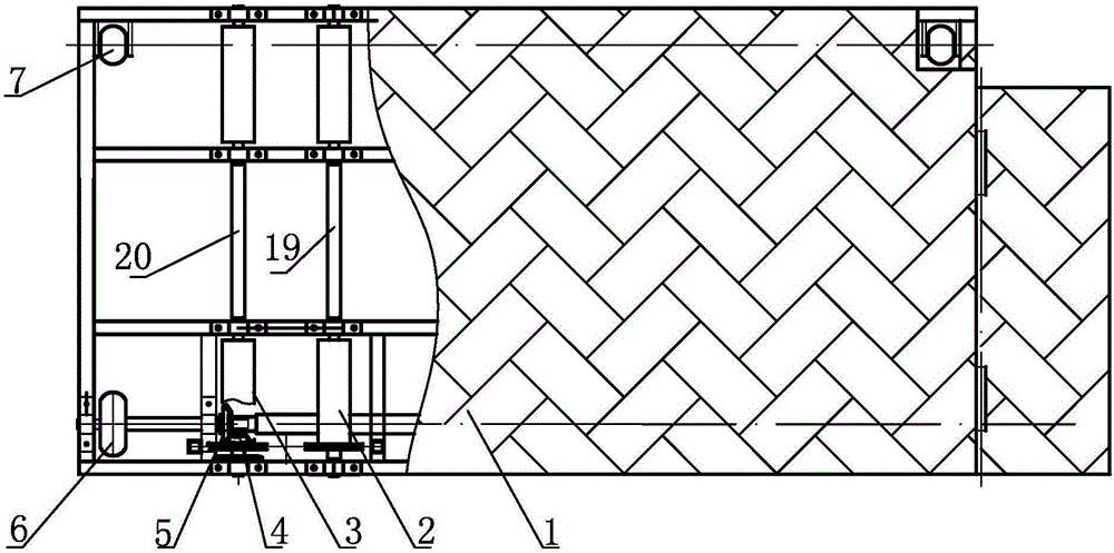
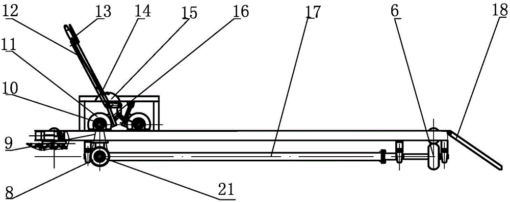
[0009] Specific implementation mode one: combine Figure 1 to Figure 2 Describe this embodiment, a self-driven roadside parking auxiliary device described in this embodiment includes a mobile platform 1, two wheel support wheels 2, two main driving wheels 3, a bevel gear driving wheel 4, and a bevel gear driven wheel 5 , two platform drive wheels 6, two platform support wheels 7, large sprocket 8, transmission chain 9, small sprocket 10, braking mechanism, transmission shaft 17, folding ramp 18, first rotating shaft 19 and second rotating shaft 20. The transition shaft 21, the mobile platform 1 is a rectangular plate body arranged horizontally, the two platform support wheels 7 are arranged on one side of the lower surface of the mobile platform 1 along the length direction of the mobile platform 1, and the two platform drive wheels 6 are arranged along the direction of the mobile platform 1. The length direction is arranged on the other side of the lower surface of the mobile...

specific Embodiment approach 2

[0011] Specific implementation mode two: combination Figure 1 to Figure 4 Describe this embodiment, a self-driven type described in this embodiment The braking mechanism of the roadside parking auxiliary device comprises a brake hub 11, a brake handle 12, a brake positioning handle 13, a brake Moving locating pin 14, brake locating disc 15, brake 16 and support 23, brake 16 is connected with small wheel hub 11 by brake The sprocket 10 is connected, the positioning disc 15 is installed on the bracket 21, the lower end of the brake handle 12 is connected with the brake 16, and the system The dynamic positioning handle 13 is installed on the upper end of the brake handle 12, and the brake positioning pin 14 is installed on the bottom of the brake handle 12, And the upper end of brake locating pin 14 is connected with brake locating handle 13 by connecting rod, and the lower end of brake locating pin 14 is connected with brake locating handle 13. The positioning disc 1...

specific Embodiment approach 3

[0012] Specific implementation mode three: combination Figure 3 to Figure 4 To illustrate this embodiment, the self-driven on-street parking auxiliary device described in this embodiment further includes a rotating central turntable 22 installed at a corner of one end of the mobile platform 1 .

[0013]In this embodiment, the mobile flat parking platform is changed from parallel movement to a fixed point as the rotation center, and the parking mobile platform is moved in or out by rotation. The present invention is composed of a mobile platform 1, a wheel support wheel 2, a main driving wheel 3, Bevel tooth driving wheel 4, bevel tooth driven wheel 5, platform driving wheel 6, universal wheel 7, large sprocket 8, transmission chain 9, small sprocket 10, brake hub 11, brake handle 12, brake positioning handle 13, Brake positioning pin 14, brake positioning disc 15, brake 16, power transmission shaft 17, folding slope plate 18, transition shaft 21, rotation center rotating disk...


PUM


Abstract

The invention discloses a self-driven roadside-parking aid device, relates to a roadside-parking aid device, particularly relates to a self-driven roadside-parking aid device and aims to solve the problem of traffic jam caused by difficulty of parking roadside of small vehicles in the prior art. The self-driven roadside-parking aid device comprises a movable platform, two vehicle wheel supporting rollers, two main driving wheels, a conical-tooth driving wheel, a conical-tooth driven wheel, two platform driving wheels, two platform supporting wheels, a large chain wheel, a driving chain, a small chain wheel, a brake mechanism, a driving shaft, a foldable slope plate, a first rotation shaft, a second rotation shaft and a transition rotation shaft, wherein the movable platform is a horizontally-disposed rectangular plate body; the two platform supporting wheels are arranged on one side of the lower surface of the movable platform along the length direction of the movable platform. The self-driven roadside-parking aid device is applied to the field of traffic and transportation.

Description

technical field [0001] The invention relates to a roadside parking auxiliary device, in particular to a self-driven roadside parking auxiliary device, which belongs to the field of transportation. Background technique [0002] Urban traffic congestion ensures the smooth passage of motor vehicles, greatly improves the functions of urban traffic facilities, and will generate huge social benefits and economic value. Effective use of the transitional space between urban motor vehicle lanes and pedestrian roads to park small vehicles to reduce the occurrence of traffic problems caused by transitional occupancy of motor vehicle lane space will play a very important role in alleviating and improving urban traffic conditions. [0003] Due to the continuous improvement of people's lives, a large number of residents who buy cars as a means of transportation have emerged, and the number of cars in cities and towns has grown rapidly. The road congestion in cities is particularly promine...

Claims


Application Information

Patent Timeline
Patent Type & Authority Applications(China)
IPC IPC(8): B60S13/00B60S13/02
Inventor 梅芳白宇博肖玉生
Owner 肖玉生
Why Eureka
Try Eureka