A Wing Torsion Mechanism for Improving the Lift of Flapping Wing Flight

A wing and lift technology, applied in the field of wing torsion design principles and structures, can solve problems such as poor aerodynamic performance and complex structure, and achieve the effect of simple structure, good aerodynamic performance and simplified structure

Inactive Publication Date: 2018-03-09
BEIHANG UNIV
View PDF5 Cites 0 Cited by
  • Summary
  • Abstract
  • Description
  • Claims
  • Application Information

AI Technical Summary

Problems solved by technology

[0005] The technical problem solved by the invention: aiming at the demand for high lift-to-weight ratio in the field of micro-flapping-wing aircraft, and considering the defects such as complex structure and poor aerodynamic performance in the wing torsion design of the existing micro-flapping-wing aircraft, it provides an improved flapping-wing flight The wing torsion mechanism of the lifting force improves the aerodynamic performance, increases the lift-to-weight ratio of the system, and simplifies the structure, making the micro flapping wing aircraft more miniaturized

Method used


Image

  • A Wing Torsion Mechanism for Improving the Lift of Flapping Wing Flight
  • A Wing Torsion Mechanism for Improving the Lift of Flapping Wing Flight
  • A Wing Torsion Mechanism for Improving the Lift of Flapping Wing Flight

Examples


Embodiment Construction

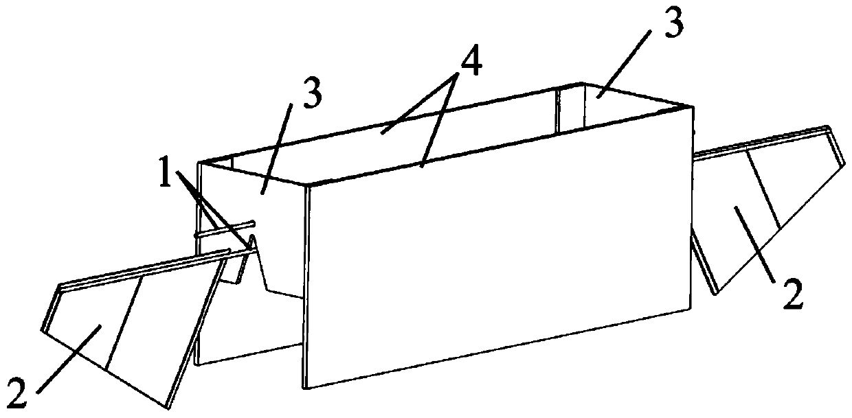
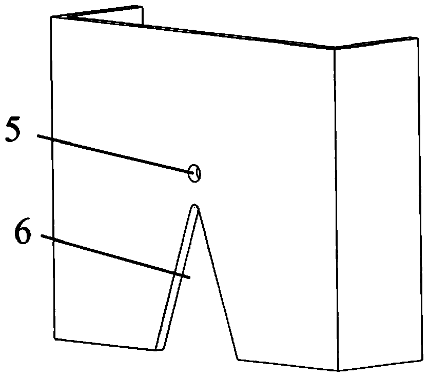
[0018] like figure 1 As shown, the present invention provides an implementation example of a wing torsion mechanism for improving flapping flight lift, including: composite beam 1, wing 2, support 3 (designed with support hole 5 and limit angle 6), and electrode 4. Among them, the composite beam 1 and the wings 2 form a beam-wing structure, the support 3 provides support for the composite beam 2 and the electrode 4, the upper side beam of the composite beam passes through the supporting holes on the supports on both sides, and the lower side beam and wings are placed in the limit angle.

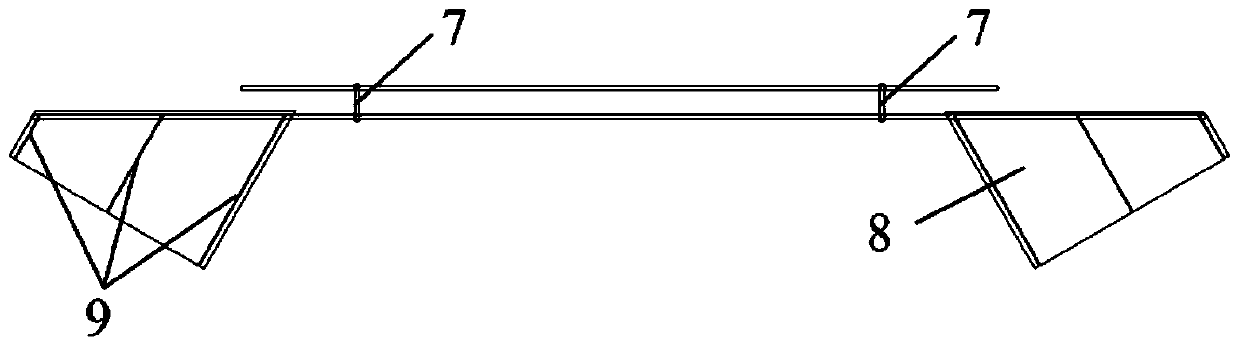
[0019] like figure 2 As shown, the composite beam is composed of two upper and lower single beams, which are connected and fixed by two short beams 7 on both sides of the beam, and the lower side beam is connected with the wing and used as the wing spar. A single wing is composed of a film 8 and three The short beam 9 constitutes. Among them, the length of the upper side beam of the compo...


PUM


Abstract

A wing torsion mechanism for improving the flight lift of a flapping wing, comprising: a combined double beam that drives the wings through the vibration of the combined double beam; two wings that provide aerodynamic lift; two supports with two support holes distributed on each side One each, as the fulcrum of wing twisting, two limit angles, one on each side, provide space for wing twisting and limit the maximum angle of wing twisting; two electrodes, respectively connected to the positive and negative poles of the DC power supply, are used to stimulate the combined double Vibration of the beam. Different from the wing torsion design mechanism of the existing miniature flapping wing aircraft, the invention realizes the torsion action of the wings through the support hole and the limit angle, and can realize a better combination of wing flapping and torsion while simplifying the structure, with better Excellent aerodynamic performance, which can greatly improve the lift of flapping wing flight.

Description

technical field [0001] The invention relates to a wing torsion design principle and structure for improving the lift force of flapping wings, and belongs to the field of aerodynamics and miniature flapping wings aircraft. Background technique [0002] Micro flapping-wing aircraft has better aerodynamic efficiency and maneuverability than fixed-wing and rotary-wing aircraft in the centimeter or millimeter scale, and has broad application prospects in military reconnaissance and infiltration, civilian detection and search and rescue. In order for the miniature flapping-wing aircraft to fly off the ground, the first consideration is to increase the lift generated when the wings flap, and increase the lift-to-weight ratio (the ratio of lift to its own gravity). Only when the lift-to-weight ratio exceeds 1, can the miniature flapping-wing aircraft Achieve off-the-ground flight. [0003] In order to generate effective lift in flapping flight, the wings cannot simply flap back and...

Claims


Application Information

Patent Timeline
Patent Type & Authority Patents(China)
IPC IPC(8): B64C33/02
Inventor 闫晓军刘志伟漆明净
Owner BEIHANG UNIV
Why Eureka
Try Eureka