Bimetal spiral steel pipe and manufacturing method thereof

A technology of spiral steel pipe and manufacturing method, which is applied in the direction of pipes, rigid pipes, pipes/pipe joints/pipe fittings, etc., can solve the problems of increasing the rigidity of the pipe body, hidden dangers of cracking, cracking of welds, etc., to increase the circumferential moment of inertia, reduce Corrosion, the effect of a large increase in cross-sectional area

Active Publication Date: 2015-12-16
南京大得钢管有限公司
View PDF5 Cites 1 Cited by
  • Summary
  • Abstract
  • Description
  • Claims
  • Application Information

AI Technical Summary

Problems solved by technology

There are the following defects: ①. The pipe body and the reinforcement ring are two separate parts, which are connected as a whole by the weld. When the reinforcement ring is stressed, the weld seam is a stress concentration area and there is a hidden danger of cracking; ②. In the process of rolling and bending Among them, because the weld seam is outside the processing deformation zone, the weld seam is stretched, deformed greatly, and is easy to crack; ③, if the pipe body is subjected to dynamic load for a long time, such as subways, vehicles, etc., the weld seam is very easy to crack due to dynamic load fatigue. Cracking; ④. In view of the semi-flexible structure of this type of pipe body, especially when the pipe body with large diameter relies heavily on the joint force effect of pipe and soil (that is, the joint deformation of the pipe body and the surrounding backfill soil), it should be increased The rigidity of the pipe body itself to avoid large deformation

Method used


Image

  • Bimetal spiral steel pipe and manufacturing method thereof
  • Bimetal spiral steel pipe and manufacturing method thereof
  • Bimetal spiral steel pipe and manufacturing method thereof

Examples


Embodiment 1

[0058] Example 1: The inner wall completely covers the pipe body with the auxiliary inner steel belt

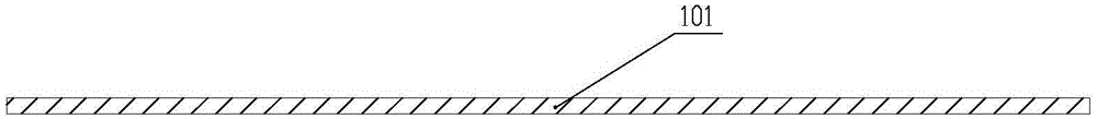
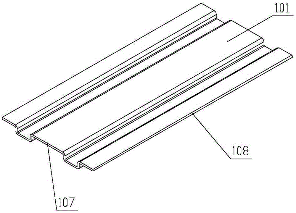
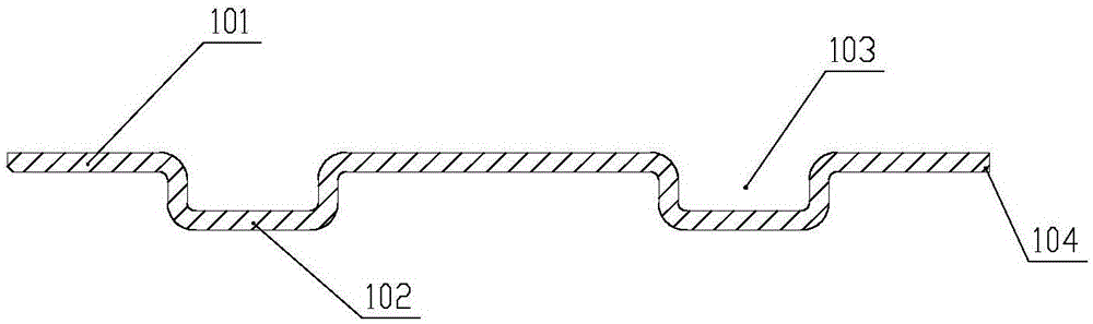
[0059] First, adjust the spiral tube forming machine to a suitable forming angle according to the diameter of the spiral welded steel pipe to be produced. Secondly, after the main steel strip 101 is derusted and shot-peened, it is rolled into a cross-sectional shape with a certain spacing and regular downward protrusions (number and size are set according to actual conditions) through a forming unit. Referred to as "beads 102", correspondingly, grooves 103 are formed above the ribs 102, and then welding slits 104 are processed on both sides of the main steel strip, such as Figure 1-3 shown. Then, a certain amount of plugging steel strips 500 are laid on the notch position of the groove 103 after the main steel strips have been formed, and the two are welded together to form a closed hollow cavity 300, such as Figure 4 shown. On the upper surface of the main steel strip 1...

Embodiment 2

[0060] Example 2: The inner wall partially covers the pipe body with the auxiliary inner steel belt

[0061] First, adjust the spiral tube forming machine to a suitable forming angle according to the diameter of the spiral welded steel pipe to be produced. Secondly, after the main steel strip 101 is derusted and shot-peened, it is rolled into a cross-sectional shape with a certain spacing and regular downward protrusions (number and size are set according to actual conditions) through a forming unit. It is called "bead 102", correspondingly, a groove 103 is formed above the rib 102, and then welding cutouts 104 are processed on both sides of the main steel strip. Next, a certain number of plugging steel strips 500 are laid on the notch position of the formed groove 103 of the main steel strip, and the two are welded together to form a closed hollow cavity 300, thus obtaining a composite steel strip. The composite steel strip formed above is sent into the rolling mechanism 700...


PUM


Abstract

The invention discloses a bimetal spiral steel pipe and a manufacturing method thereof. The steel pipe comprises a pipe body, wherein the pipe body surface extends outwards to form a convex rib which is spirally arranged around the outer wall of the pipe body; the convex rib forms a groove with the pipe body surface and is provided with an auxiliary inner steel band capable of covering the groove notch; and a hollow cavity is formed between the groove and auxiliary inner steel band, and is filled with concrete. The convex rib on the outer wall of the pipe body and the pipe body are integrally formed without any welding seam, and thus, can resist the dynamic load fatigue when bearing the dynamic load. The pipe body inner wall is provided with the auxiliary inner steel band made of a specific metal material, thereby enhancing the corrosion resistance and wear resistance of the steel pipe, avoiding the fluid pollution, reducing the thickness of the steel pipe main body and lowering the material cost. The pipe can be used in the occasions for delivering water or other special media, such as supply or discharge of water, high-corrosivity media, media with higher requirements for purity, high-temperature media and the like, and greatly lowers the manufacturing cost.

Description

technical field [0001] The invention discloses a steel pipe and a manufacturing method thereof, in particular to a bimetal spiral steel pipe and a manufacturing method thereof. Background technique [0002] At present, in the transportation, storage and transportation of fluids, pipelines are generally used for transportation. Commonly used pipelines include cement pipes, plastic pipes, ordinary carbon steel pipes, stainless steel pipes, and galvanized steel pipes. Among them, the cement pipe is a prefabricated pipe made of cement and steel bars and using the principle of centrifugal force, but it is easy to leak and has poor internal pressure resistance; and the caliber is not large, generally 3 meters or less; each section of pipe The length is not long, there are many joints, the joints are easy to leak, and the construction is difficult; the foundation must be made first during construction, and the construction cost is relatively high. Plastic pipe is made of plastic r...

Claims


Application Information

Patent Timeline
Patent Type & Authority Applications(China)
IPC IPC(8): F16L9/16
CPCF16L9/02F16L9/165
Inventor 战福军
Owner 南京大得钢管有限公司
Why Eureka
Try Eureka