Inductive reactance decreasing linear controllable inductor, electronic circuit and electromechanical equipment

An inductor and linear technology, applied in the field of electricity, can solve the problems of high cost of inductors, difficulty in using high-power circuits, complex and fragile results, etc., and achieve the effect of long service life, not easy to burn out, and low cost

Inactive Publication Date: 2015-12-16
刘伟
View PDF7 Cites 3 Cited by
  • Summary
  • Abstract
  • Description
  • Claims
  • Application Information

AI Technical Summary

Problems solved by technology

[0002] In the prior art, there are few inductors with real-time controllable inductance values, or the cost

Method used


Image

  • Inductive reactance decreasing linear controllable inductor, electronic circuit and electromechanical equipment
  • Inductive reactance decreasing linear controllable inductor, electronic circuit and electromechanical equipment
  • Inductive reactance decreasing linear controllable inductor, electronic circuit and electromechanical equipment

Examples


Embodiment 1

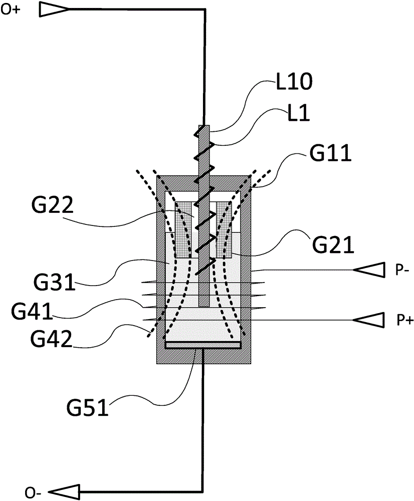
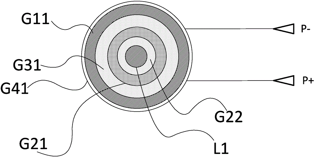
[0035] Implementation example 1, such as Figure 1-2 As shown, a linear controllable inductor with decreasing inductance includes an insulating container G11, a conductive liquid G31, a floating body G21, a common electrode G51, a winding rod L10, an inductance coil L1, an electromagnetic coil G41, and a first controlled path Node O+, the second node O- of the controlled path, the first node P+ of the control end, and the second node P- of the control end;

[0036] The insulating container G11 has a stable shape. The shape of the insulating container G11 is cylindrical, and the container of the insulating container G11 is cylindrical.

[0037] The conductive liquid G31 is contained in the cavity of the insulating container G11, the volume of the conductive liquid G31 is smaller than the volume of the insulating container G11, and the volume of the conductive liquid G31 is larger than half of the volume of the insulating container G11;

[0038] The electromagnetic coil G41 is ...

Embodiment 2

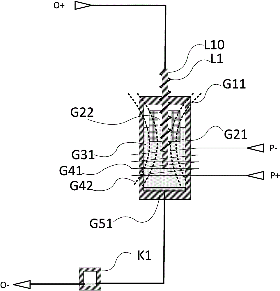
[0048]Implementation Example 2: A modification is made on the basis of implementation example 1, so that a tilt switch K1 is connected in series between the common electrode G51 and the second node O- of the controlled channel, so as to prevent the inductor from being used when it is placed incorrectly.

Embodiment 3

[0049] Embodiment 3. An electromechanical device having the linear controllable inductor with decreasing inductance described in Embodiment 1.


PUM


Abstract

The invention provides an inductive reactance decreasing linear controllable inductor. The inductor is characterized by comprising an insulated vessel (G11), a conducting liquid (G31), a floating body (G21), a common electrode (G51), a winding rod (L10), an inductance coil (L1), an electromagnetic coil (G41), a controlled path first node (O+), a controlled path second node (O-), a control terminal first node (P+) and a control terminal second node (P-). An electronic circuit comprises the controllable inductor. Electromechanical equipment comprises the controllable inductor. The inductor has long contact life and good isolation, is low in cost and can be applied to high-power circuits, such as weak-current power circuits, power circuits and ultrahigh-voltage power circuits.

Description

technical field [0001] The invention belongs to the field of electricity, in particular to a linear controllable inductor with decreasing inductance, an electronic circuit and electromechanical equipment. Background technique [0002] In the prior art, there are few inductors with real-time controllable inductance, or the cost is too high, or the result is complex and vulnerable, or it is difficult to be used in high-power circuits. Contents of the invention [0003] In order to solve the problems described in the technical background, the present invention proposes linear controllable inductors, electronic circuits, and electromechanical devices with decreasing inductance. [0004] The present invention has the following technical contents. [0005] 1. A linear controllable inductor with decreasing inductance, characterized in that it includes an insulating container (G11), a conductive liquid (G31), a floating body (G21), a common electrode (G51), a winding rod (L10), ...

Claims


Application Information

Patent Timeline
IPC IPC(8): H01F29/00H01F27/28
Inventor 刘伟
Owner 刘伟
Why Eureka
Try Eureka