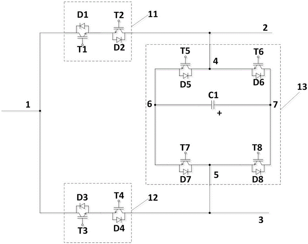
DC power supply power flow controller topology
A technology of power flow controller and DC power grid, which is applied in the direction of DC network circuit devices, electrical components, circuit devices, etc., can solve the problems of high technical difficulty and increased system operation loss, and achieves small size, low withstand voltage requirements, and easy engineering. effect achieved
- Summary
- Abstract
- Description
- Claims
- Application Information
AI Technical Summary
Problems solved by technology
Method used
Image
Examples
Embodiment 1
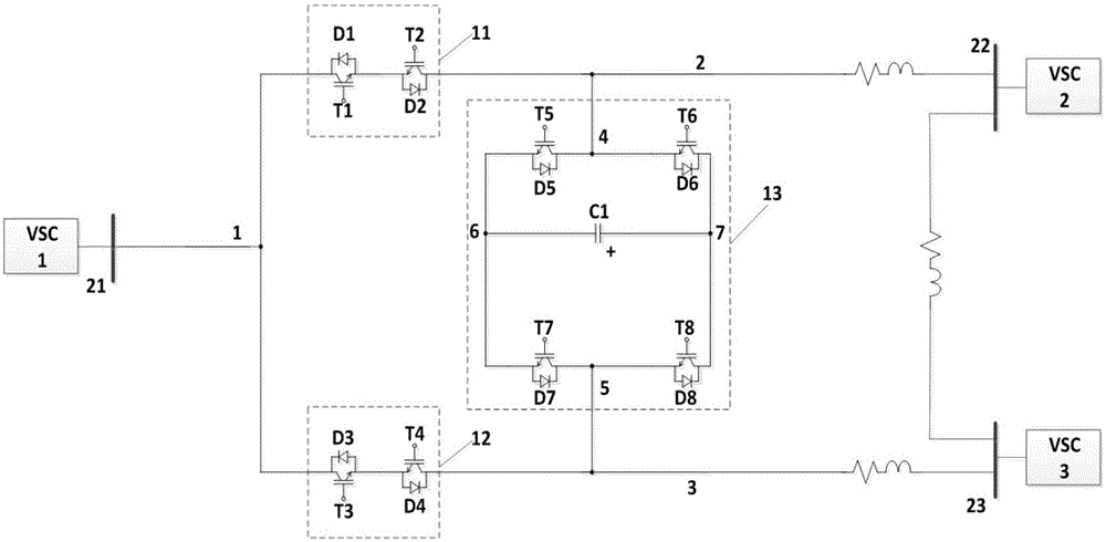
[0033] figure 2 Shown is the specific implementation of the DC grid power flow controller connected to the three-terminal DC ring network, wherein the first lead-out terminal 1 of the power flow controller is connected to the first converter station 21, and the second lead-out terminal 1 of the power flow controller The terminal 2 is connected to the second converter station 22 through the direct current transmission line, and the third lead-out terminal 3 of the power flow controller is connected to the third converter station 23 through the direct current transmission line.
Embodiment 2
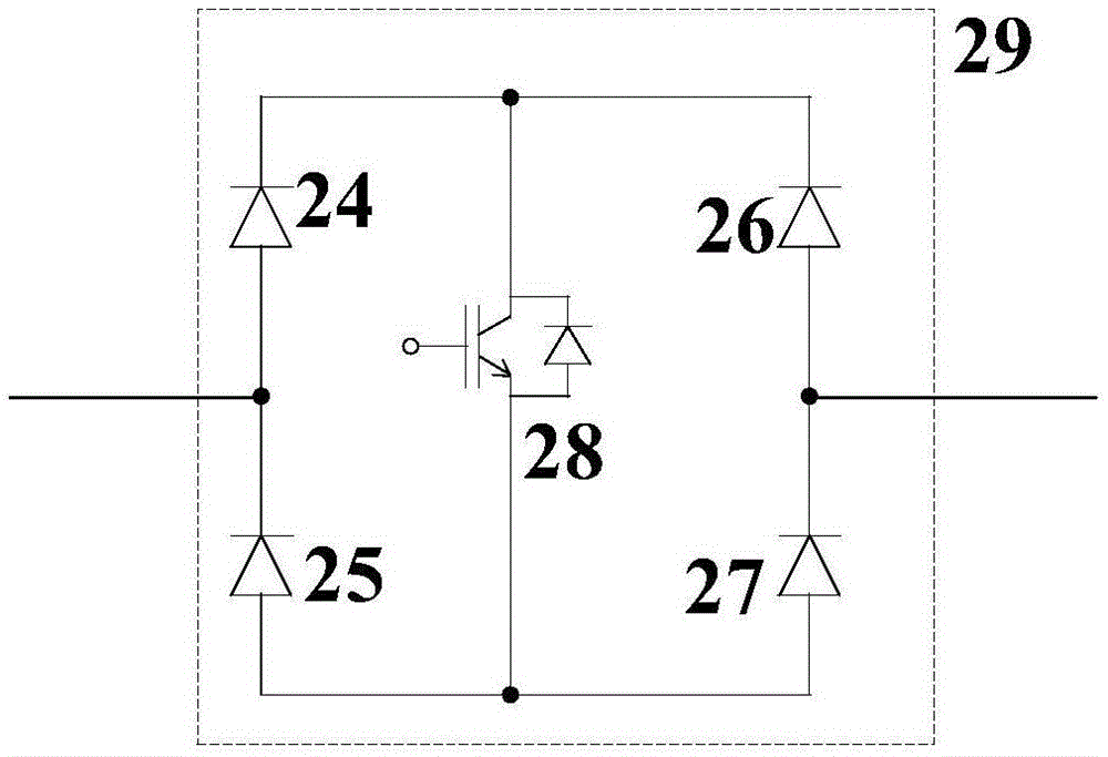
[0035] image 3 An alternative implementation of the guided switch module is shown. Such as image 3 As shown, the guide switch module is composed of four diodes 24 , 25 , 26 , 27 and a fully controlled device 28 . The cathode of the first diode 24 is connected with the cathode of the second diode 26, and is connected with the collector of the fully controlled device 28; the anode of the third diode 25 is connected with the anode of the fourth diode 27, And be connected with the emitter electrode of full control type device 28; The anode of the first diode 24 is connected with the cathode of the third diode 25, as the first lead-out terminal of guide switch; The anode of the second diode 26 is connected with the cathode of the third diode 25. The cathodes of the four diodes 27 are connected as the second lead-out terminal of the pilot switch.
Embodiment 3
[0037] Figure 4 Shown is another implementation of the power flow controller. Such as Figure 4 As shown, the full-bridge sub-modules are replaced by a full-bridge sub-module cascade structure 33 . The full-bridge sub-module cascade structure 33 is composed of a first full-bridge sub-module 31 and a second full-bridge sub-module 32 in cascade. The first lead-out terminal 34 of the second full-bridge sub-module 32 is connected to the second lead-out terminal 45 of the first full-bridge sub-module 31, and the second lead-out terminal of the first guide switch module 11 is connected to the second lead-out terminal of the first full-bridge sub-module 31. One lead-out terminal 44 is connected, the connection point is used as the second lead-out terminal 2 of the DC power flow controller, the second lead-out terminal of the second guide switch module 12 is connected to the second lead-out terminal 35 of the second full-bridge sub-module 32, The connection point serves as the thi...
PUM
 Abstract
Description
Claims
Application Information
 - R&D
- Intellectual Property
- Life Sciences
- Materials
- Tech Scout
- Unparalleled Data Quality
- Higher Quality Content
- 60% Fewer Hallucinations
Browse by: Latest US Patents, China's latest patents, Technical Efficacy Thesaurus, Application Domain, Technology Topic, Popular Technical Reports.
© 2025 PatSnap. All rights reserved.Legal|Privacy policy|Modern Slavery Act Transparency Statement|Sitemap|About US| Contact US: help@patsnap.com


