Z-source matrix rectifier and vector modulation method thereof

A technology of matrix rectifiers and rectifiers, which is applied in the field of rectifiers and can solve problems affecting circuit reliability and other issues

Active Publication Date: 2015-12-16
HARBIN INST OF TECH
View PDF4 Cites 6 Cited by
  • Summary
  • Abstract
  • Description
  • Claims
  • Application Information

AI Technical Summary

Problems solved by technology

[0005] The purpose of the present invention is to solve the problem that the output DC voltage of the matrix rectifier is lower than the input line voltage and the open circuit on the input side will affect the reliability of the circuit, and provides a Z-source matrix rectifier and its vector modulation method

Method used


Image

  • Z-source matrix rectifier and vector modulation method thereof
  • Z-source matrix rectifier and vector modulation method thereof
  • Z-source matrix rectifier and vector modulation method thereof

Examples


specific Embodiment approach 1

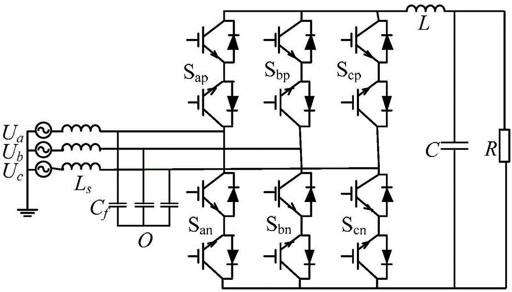
[0084] Specific implementation mode one: the following combination figure 2 Describe this embodiment, the Z source matrix rectifier described in this embodiment, it includes input filter, matrix rectifier and output filter, it also includes Z source network,

[0085] The input end of the input filter is connected to the three-phase power supply, the output end of the input filter is connected to the input end of the matrix rectifier, the output end of the matrix rectifier is connected to the input end of the Z source network, and the output end of the Z source network is connected to the input end of the output filter , the output voltage of the output terminal of the output filter supplies power to the load.

specific Embodiment approach 2

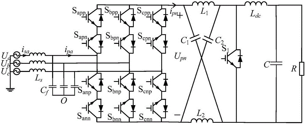
[0086] Specific implementation mode two: the following combination Figure 2 to Figure 18 Describe this implementation mode. This implementation mode will further describe the first implementation mode. The Z source network includes a capacitor C 1 , capacitance C 2 , inductance L 1 , inductance L 2 and IGBT S 1 ,

[0087] An inductor L is connected between the positive output terminal of the matrix rectifier and the positive input terminal of the output filter 1 , the inductor L is connected between the negative output terminal of the matrix rectifier and the negative input terminal of the output filter 2 , a capacitor C is connected between the positive output of the matrix rectifier and the negative input of the output filter 1 , a capacitor C is connected between the negative output terminal of the matrix rectifier and the positive input terminal of the output filter 2 , the positive input of the output filter is connected to the insulated gate bipolar transistor S ...

specific Embodiment approach 3

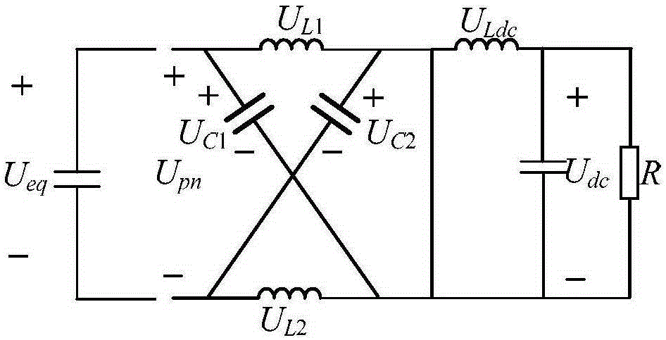
[0089] Specific implementation mode three: the following combination Figure 2 to Figure 18 Describe this embodiment, the vector modulation method of the Z source matrix rectifier described in this embodiment, the modulation method is realized based on the above-mentioned Z source matrix rectifier, and the Z source matrix rectifier is set to the following state one and state two respectively:

[0090] State one: make the IGBT S 1 conduction, the switching tubes of the matrix rectifier are all turned off, and at this time the Z source network is disconnected from the matrix rectifier; the state of the switching tubes of the matrix rectifier being completely turned off is called an open state;

[0091] State two: make the IGBT S 1 Not conducting, the matrix rectifier is in the normal working state, at this time, the matrix rectifier and the time Z source network provide energy for the load at the same time; the normal working state of the matrix rectifier is called a non-open c...


PUM


Abstract

The invention discloses a Z-source matrix rectifier and a vector modulation method thereof, and belongs to the technical field of a rectifier, for solving the problems that output DC voltage of a conventional matrix rectifier is smaller than input line voltage and an open circuit at an input side affects circuit reliability. The input end of an input filter of the rectifier is connected with a three-phase power source, the output end of the input filter is connected with the input end of the matrix rectifier, the output end of the matrix rectifier is connected with the input end of a Z-source network, the output end of the Z-source network is connected with the input end of an output filter, and the output end of the output filter outputs voltages for supplying power to a load. According to the method, through determining an instantaneous value and a zero-crossing point of three-phase voltages, a sector is determined, under the condition that unit power factors of voltages and currents at the input side are guaranteed, an input reference current vector is determined, and the duty ratio value of the corresponding vector is obtained through a calculation formula, such that a vector modulation strategy is realized. The Z-source matrix rectifier and the vector modulation method thereof are applied to a rectifier and modulation of the rectifier.

Description

technical field [0001] The invention relates to a Z-source matrix rectifier and a vector modulation method thereof, belonging to the technical field of rectifiers. Background technique [0002] Rectifiers are widely used in the fields of synchronous generator excitation, DC motor speed regulation, high-voltage DC transmission system, renewable energy utilization and household appliances. The initial requirement for the rectifier is mainly to realize the function of rectification, but with the increasing energy shortage and environmental problems in the world, the requirement of "green environmental protection" has been added to the rectifier, which needs to save energy to the greatest extent. At present, the main form of rectifier is PWM rectifier. The main defects in its use are: large-capacity energy storage elements are required in the structure; lack of flexibility in four-quadrant movement; In the middle, it is necessary to add a power frequency transformer on the inpu...

Claims


Application Information

Patent Timeline
Patent Type & Authority Applications(China)
IPC IPC(8): H02M7/217
Inventor 刘洪臣赵丹纪玉亮
Owner HARBIN INST OF TECH
Why Eureka
Try Eureka