
Asymmetric triangle frequency modulation radar communication integrated signal waveform determination method

A technology of triangular frequency modulation and signal waveform, applied in frequency modulation carrier system, modulated carrier system, radio wave measurement system, etc., can solve the problems of low communication spectrum efficiency, affecting radar detection performance, radar range and resolution change, etc.

Active Publication Date: 2015-12-16
XIAN INSTITUE OF SPACE RADIO TECH
View PDF5 Cites 12 Cited by
  • Summary
  • Abstract
  • Description
  • Claims
  • Application Information

AI Technical Summary

Problems solved by technology

[0004] The integrated system based on waveform sharing is still in its infancy. The shared signal is mainly chirp, and the communication information is modulated by changing the parameters of the chirp signal. However, this method changes the bandwidth and time width of the signal, making The range and resolution of the radar will change, thus affecting the detection performance of the radar
[0005] In the integrated waveform design based on fractional Fourier transform, different initial frequencies are used to modulate user data to achieve the transmission of multi-bit information of a single Chirp signal, but the common disadvantage of this type of system is that the communication transmission rate is different from Chirp Rate is related, under the same bandwidth condition, the spectrum efficiency of communication is low

Method used


Image

  • Asymmetric triangle frequency modulation radar communication integrated signal waveform determination method
  • Asymmetric triangle frequency modulation radar communication integrated signal waveform determination method
  • Asymmetric triangle frequency modulation radar communication integrated signal waveform determination method

Examples


Embodiment

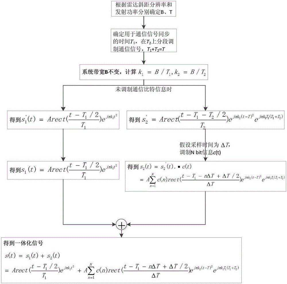
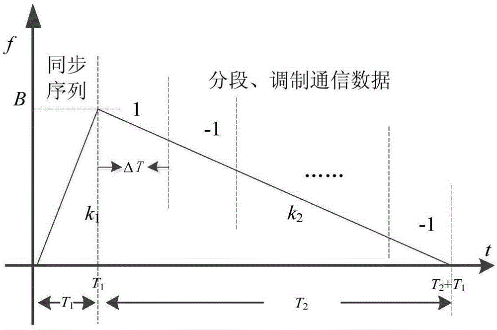
[0073] Such as figure 1 Shown is a block diagram of the processing flow of the present invention, by figure 1 It can be seen that the present invention proposes an asymmetric triangular frequency modulation radar communication integrated signal waveform, and the specific implementation steps are as follows:

[0074] (1) Assume that the system bandwidth B=70MHz, and the time width T=500us;

[0075] (2) Assuming T 1 = 100us, T 2 =T-T 1 =400us;

[0076] (3) According to steps (1) and (2), calculate k 1 =(70×10 6 ) / (100×10 -6 )=0.7×10 12 ;K 2 =-(70×10 6 ) / (400×10 -6 )=-0.175×10 12 ;

[0077] (4) According to steps (2) and (3), get the signal s 1 '(t), s 2 '(t) expression:

[0078] s 1 , ( t ) = 1 / 5 X 10 - 4 · r e c t ( t - 10 - 4 / 2 10 - 4 ) e - j · 0.7 · 10 12 · πt 2

[0079] s 2 , ( t ) = 1 / 5 × 10 - 4 · r e c ...


PUM


Abstract

The invention discloses an asymmetric triangle frequency modulation radar communication integrated signal waveform determination method. An integrated signal waveform is an asymmetric triangle and is composed of two segments of liner frequency modulation signals with opposite frequency modulation rate symbols. First of all, a bandwidth B and a time width T of an integrated system are determined; the system time width T is divided into two segments, and time lengths are respectively T1 and T2; the tuning rate symbols of the two segments of the linear frequency modulation signals are opposite, the bandwidth B is the same, and tuning rates of the two segments of the linear frequency modulation signals are respectively calculated; the first segment of signals are used for synchronous capture of communication signals, and communication information is not modulated; for the second segment of signals, communication bit information is modulated segment by segment; and phase continuity of the two segments of signals is ensured, and an expression of integrated signals on the whole time width T is finally obtained. According to the invention, waveform integration of a radar and the communication signals can be realized, a part of integrated signals are taken as a synchronization sequence for synchronization of a communication system, the communication bit information is modulated segment by segment for the residual part of the integrated signals, and the whole integrated signals are taken as radar emission signals.

Description

Technical field [0001] The present invention proposes an asymmetric triangular frequency modulation radar communication integrated signal waveform determination method, which can be applied to the integrated radar communication waveform design based on signal sharing, and belongs to the field of radar communication waveform modulation. Background technique [0002] With the development of technology and the needs of information warfare, the form of war has changed from a single weapon platform confrontation to a system confrontation. The realization of the integrated integration of multi-functional electronic systems has become the development trend of future military electronic systems. The integration of radar communication signals is of great significance for improving the comprehensive performance of electronic systems. Exploring the design method of integrated waveform is the key research content of radar communication signal integration technology. [0003] In the process of...

Claims


Application Information

Patent Timeline
Patent Type & Authority Applications(China)
IPC IPC(8): H04L27/10G01S7/35
CPCG01S7/35H04L27/103
Inventor 孙召黎薇萍王显煜石俊峰
Owner XIAN INSTITUE OF SPACE RADIO TECH
Learn More