An improved thyristor dimming drive circuit for LED lamps

A driving circuit and LED lamp technology, applied in the direction of lamp circuit layout, light source, electric light source, etc., can solve the problems of poor compatibility, LED flickering, etc., and achieve the effect of large ripple output, simple structure and strong compatibility

Active Publication Date: 2018-08-21
GUANGDONG REAL DESIGN INTELLIGENT TECH
View PDF4 Cites 0 Cited by
  • Summary
  • Abstract
  • Description
  • Claims
  • Application Information

AI Technical Summary

Problems solved by technology

[0005] The purpose of the present invention is to provide an improved thyristor dimming drive circuit for LED lamps in order to overcome the problems of poor compatibility between the prior art thyristor dimming circuit and LED driver and the problems of easily causing LED flickering

Method used


Image

  • An improved thyristor dimming drive circuit for LED lamps
  • An improved thyristor dimming drive circuit for LED lamps

Examples


specific Embodiment

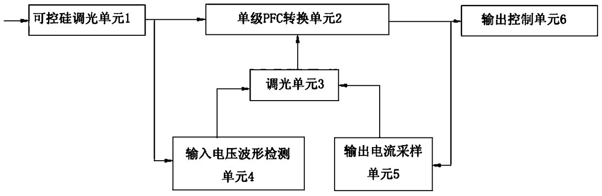
[0022] refer to figure 1 , this embodiment includes a thyristor dimming unit 1, the output end of the thyristor dimming unit 1 is provided with a single-stage PFC conversion unit 2, a dimming unit 3, an input voltage waveform detection unit 4, an output current sampling unit 5 and an output Control unit 6; the input end of the thyristor dimming unit 1 is connected to the mains, the output end is connected to the input end of the single-stage PFC conversion unit 2 and the input end of the input voltage waveform detection unit 4, and the output end of the single-stage PFC conversion unit 2 Connect the input end of the output control unit 6, the output control unit 6 has a constant current voltage output end and a power input end for externally connecting LED lamps; the input end of the output current sampling unit 5 is connected to the output end and the output end of the single-stage PFC conversion unit 2 terminal is connected to one of the input terminals of the dimming unit 3...


PUM


Abstract

The invention relates to an improved silicon controlled LED dimming drive circuit, which comprises a silicon controlled dimming unit. The improved silicon controlled LED dimming drive circuit is characterized in that an output end of the silicon controlled dimming unit is provided with a single-stage PFC conversion unit, a dimming unit, an input voltage waveform detection unit, an output current sampling unit and an output control unit; the output end of the silicon controlled dimming unit is connected to an input end of the single-stage PFC conversion unit, an output end of the single-stage PFC conversion unit is connected to an input end of the output control unit, and the output control unit has a constant-current voltage output end and a power supply input end for external connection with an LED light; and an output end of the output current sampling unit and an output end of the input voltage waveform detection unit are connected with an input end of the dimming unit, and a control signal is outputted through the dimming unit to control the single-stage PFC conversion unit to have a constant output current. The invention has the characteristics of high compatibility, stability and reliability.

Description

technical field [0001] The invention relates to an improved thyristor dimming drive circuit for LED lamps. The invention belongs to the technical field of LED lamp dimming driving equipment (device). Background technique [0002] In the field of lighting equipment, because LED lighting is popular with people for its energy-saving and convenient and flexible dimming methods, LED lights are widely used. Since LED lamp beads are current-driven, when the current is not constant, the service life of LED lamp beads will be severely shortened. [0003] In the prior art, the dimming of LED lamps is usually connected to the thyristor dimmers in the live wire series, because these thyristor dimmers control the conduction of different phase angles of the input voltage sine wave, so that the output The effective value of the voltage changes, so as to achieve the purpose of adjusting the LED output current. Although this method realizes dimming of LED lights, it has the following disa...

Claims


Application Information

Patent Timeline
Patent Type & Authority Patents(China)
IPC IPC(8): H05B37/02
Inventor 汪军黄祖好岑锐秋
Owner GUANGDONG REAL DESIGN INTELLIGENT TECH
Why Eureka
Try Eureka