rotor for electric motor

A motor and rotor technology, applied in the field of rotors used in motors, to achieve the effect of simplifying the manufacturing process, simple and stable

Active Publication Date: 2017-09-01
SIEMENS AG
View PDF2 Cites 0 Cited by
  • Summary
  • Abstract
  • Description
  • Claims
  • Application Information

AI Technical Summary

Problems solved by technology

As a result, however, this part of the lamination stack can no longer be used to create electromagnetic torque
This creates a significant disadvantage in terms of the power of the motor

Method used


Image

  • rotor for electric motor
  • rotor for electric motor
  • rotor for electric motor

Examples


Embodiment Construction

[0029] The same parts are provided with the same reference numerals in all figures.

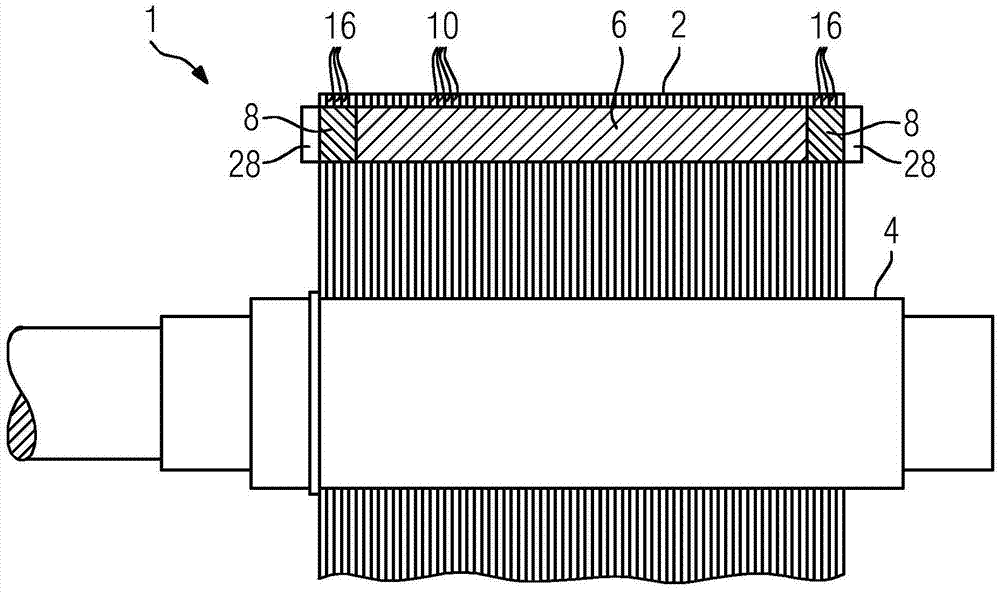
[0030] figure 1 A rotor 1 for an electric motor is shown. It is designed as a cage rotor and has a short-circuited cage running in the laminated core 2 instead of a coil wound from wire and supplied via slip rings, as in slip ring rotor motors. The rotor 1 comprises a laminated core 2 made of iron, arranged on a shaft 4 , into which metal rods 6 made of a non-ferrous metal, such as copper or aluminum, are inserted. The metal rod 6 extends substantially in the axial direction, however it is slightly inclined in the circumferential direction with respect to the axial direction. It is connected at the axial end of the laminated core 2 to a surrounding short-circuit ring 8 .

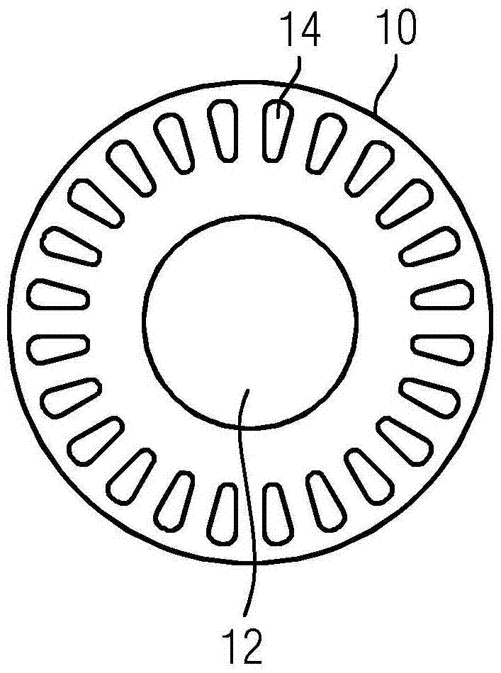
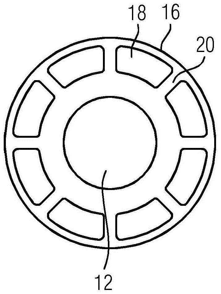
[0031] The lamination pack 2 consists of individual laminations, which are insulated from one another, into which cutouts for receiving the metal rods 6 are stamped. this is in figure 2 and 3 is further shown in . T...


PUM


Abstract

A rotor (1) for an electric motor, comprising a stack (2) of a plurality of laminations (10, 16) insulated from one another arranged on a shaft (4), the rotor being intended to operate at a particularly low Particularly high maximum rotational speeds and powers of the electric motor are permitted due to the complexity of manufacture. For this purpose, in the axial edge region of the laminated core (2), cutouts (18) are introduced in the plurality of laminations (16), which are arranged in such a way that they form a cavity surrounding the shaft (4) (twenty two).

Description

technical field [0001] The invention relates to a rotor for an electric motor, comprising a lamination pack arranged on a shaft and consisting of a plurality of laminations insulated from one another, wherein recesses are introduced into the lamination pack in the region of the axial edges of the lamination pack. In each lamination, the cutout is arranged such that it forms a cavity around the shaft. Background technique [0002] Electric motors are used to generate mechanical, usually rotational energy from electricity. In an electric motor, the force exerted by a magnetic field on a conductor of a coil through which current flows is converted into motion. For this purpose, the electric motor comprises a stationary stator and a rotor rotating therein, which is mounted in corresponding bearings. The electric motors used in most cases today are asynchronous motors. [0003] There are two designs for the rotor of an asynchronous motor: In slip ring rotor motors, the rotor h...

Claims


Application Information

Patent Timeline
Patent Type & Authority Patents(China)
IPC IPC(8): H02K17/16H02K15/00
CPCH02K17/16H02K15/0012H02K17/165
Inventor 汉斯-维尔纳·利波特
Owner SIEMENS AG
Why Eureka
Try Eureka