Sewage treatment unit capable of effectively reducing COD suspended solids (SS)

A sewage treatment device and suspended solids technology, applied in the direction of filtration and separation, separation methods, chemical instruments and methods, etc., can solve the problems of large pressing area, unsmooth water outlet channel, and small footprint, so as to increase water output and improve The effect of water flow

Inactive Publication Date: 2015-12-23
ZHEJIANG JINGANG TEXTILE PRINTING & DYEING
4 Cites 1 Cited by

AI-Extracted Technical Summary

Problems solved by technology

Its main feature is that it occupies a small area and has a large pressing area. Its disadvantages are that the water outlet c...

Abstract

The invention discloses a sewage treatment unit capable of effectively reducing COD suspended solids (SS). The sewage treatment unit comprises a filter, a hydraulic workstation, an electric cabinet, a sewage pool, a sludge sump and a clear liquid pool, wherein a thrust plate and a press plate are arranged on the filter, a filter plate and a filtration fabric are arranged between the thrust plate and the press plate; a hydraulic cylinder base is arranged on the filter, and a hydraulic cylinder is arranged on the hydraulic cylinder base; a cross beam is arranged on the filter, and a drawing plate unit is arranged on the cross beam; a first three-way pipe is arranged between a liquid inlet and the sewage pool, the first three-way pipe is connected with the sludge sump, a sludge discharge valve is arranged between the first three-way pipe and the sludge sump, a second three-way pipe is arranged on a water outlet channel, one end of the second three-way pipe is connected with a backwashing pump, the other end of the second three-way pipe is connected with the clear liquid pool, and a water outlet valve is arranged between the second three-way pipe and the clear liquid pool. The sewage treatment unit has a function of continuously filtering, has a filtering function on sewage in combination with the filter, is large in filter plate filtering area, has an effect of increasing water discharge capacity and can be used for effectively reducing the content of COD suspended solids (SS).

Application Domain

Technology Topic

Image

  • Sewage treatment unit capable of effectively reducing COD suspended solids (SS)
  • Sewage treatment unit capable of effectively reducing COD suspended solids (SS)
  • Sewage treatment unit capable of effectively reducing COD suspended solids (SS)

Examples

  • Experimental program(1)

Example Embodiment

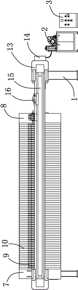
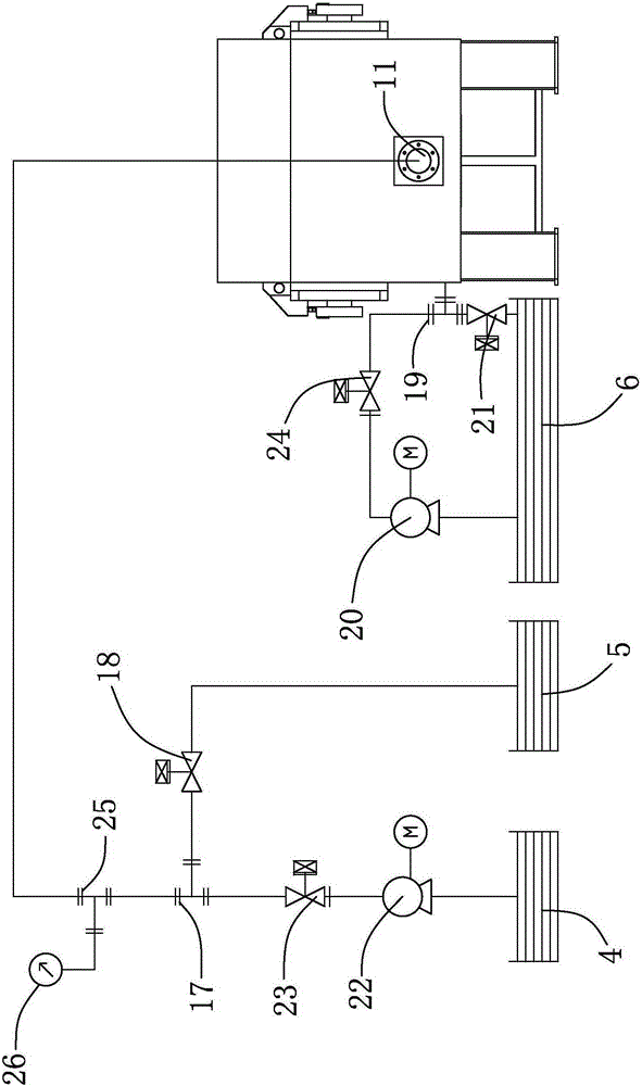
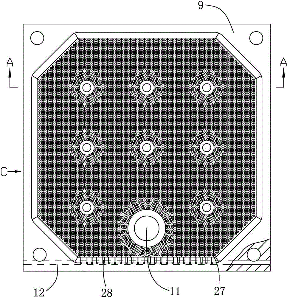
[0027] like Figure 1 to Figure 6 As shown, it is a sewage treatment device for effectively reducing COD suspended matter SS of the present invention, including a filter 1, a hydraulic workstation 2, an electric control box 3, a sewage tank 4, a sludge tank 5 and a clear liquid tank 6, and a hydraulic workstation 2 To supply energy for the filter 1, the electric control box 3 is equipped with a power indicator light, a pressure maintaining indicator light, a return indicator light, a pressing button, a return button, a pull button and an emergency stop button. The processing device controls and displays the working status. The filter 1 is provided with a thrust plate 7 and a pressing plate 8, a filter plate 9 and a filter cloth 10 are arranged between the thrust plate 7 and the pressing plate 8, a filter cavity is formed between the filter plates 9, and the filter cloth 10 is provided In the filter chamber, the filter plate 9 is provided with a liquid inlet 11, a water outlet hole 28 and a water outlet channel 12, and the liquid inlet 11 is located at the lower half of the filter plate 9, and the sewage enters the filter chamber from the liquid inlet 11, and passes through With the conversion of the valve, the liquid inlet 11 can be used for both liquid inlet and slag discharge. Increase the filtering area of ​​the filter plate 9 to sludge in the sewage, and improve the filtering effect. The filter plate 9 is provided with drainage grooves 27, and the drainage grooves 27 are evenly distributed on the filter plate 9 in a "1" shape, so as to improve the fluidity of the water outlet. The cross-section of the drainage groove 27 is semicircular, and the radius of the cross-section of the drainage groove 27 is 1-2mm. The sludge is intercepted outside the drainage groove 27, and the filtrate is discharged into the water outlet channel 12 along the drainage groove 27, which can increase the water output. At the same time improve the flow of water. For technical requirements, the boss on the filter plate 9 is not allowed to have scars and deformations, the thickness tolerance size deviation of the two sealing surfaces is ±0.5mm, and the thickness difference between the two sealing surfaces is ≤0.4mm. The filter cloth 10 adopts a double-layer fabric structure, which has the characteristics of fine texture, high strength, strong ability to capture fine particles, good peeling performance, and acid and alkali resistance. The filter 1 is provided with an oil cylinder seat 13, and the oil cylinder seat 13 is provided with an oil cylinder 14, and the oil cylinder 14 is connected with the pressing plate 8. The filter 1 is provided with a crossbeam 15, and the crossbeam 15 is provided with a pull plate mechanism 16. The liquid inlet 11 is connected to the sewage pool 4, and a first three-way pipe 17 is arranged between the liquid inlet 11 and the sewage pool 4, and the first three-way pipe 17 is connected to the sludge pool 5, and the sewage pool 4 is connected to a feed pump 22 , the feed pump 22 is connected to the first three-way pipe 17, and the feed pump 22 pumps the sewage in the sewage pool 4 into the first three-way pipe 17, and the feed pump 22 and the first three-way pipe 17 are provided with The first check valve 23 . The first check valve 23 controls the feed process of the feed pump 22 . A sludge discharge valve 18 is provided between the first three-way pipe 17 and the sludge tank 5 . A third three-way pipe 25 is arranged between the first three-way pipe 17 and the liquid inlet 11, and the third three-way pipe 25 is connected with a feed pressure gauge 26, and the feed pressure gauge 26 shows that the feed pump 22 is pumped into the pipeline flow of sewage. The outlet channel 12 is provided with a second three-way pipe 19, one end of the second three-way pipe 19 is connected with a backwash pump 20, the backwash pump 20 is connected to the clear liquid pool 6, and the connection between the second three-way pipe 19 and the backwash pump 20 A second check valve 24 is arranged between them, and the second check valve 24 controls the backwash process of the backwash pump 20 . The other end of the second three-way pipe 19 communicates with the clear liquid pool 6 , and a water outlet valve 21 is provided between the second three-way pipe 19 and the clear liquid pool 6 .
[0028]In the filtering process of the present invention, under the action of the plate pulling mechanism 16, the filter 1 is loaded with a filter plate 9, and under the force of the oil cylinder 14, the thrust plate 7 and the pressing plate 8 compress the filter plate 9, A filter cavity is formed between the filter plates 9, and the filter cloth 10 is clamped in the filter cavity. After the filter 1 is installed, the sludge discharge valve 18 is closed, the water outlet valve 21 is opened, and the sewage in the sewage pool 4 passes through the feed pump 22 , the first check valve 23 and the first three-way pipe 17 flow into the filter chamber of the filter 1 from the liquid inlet 11, the filter cloth 10 and the filter plate 9 filter the sewage, and the clear liquid flows along the filter plate 9 and The drainage groove 27 flows into the water outlet hole 28, and the clear liquid flows into the water outlet channel 12 from the water outlet hole 28, and the clear liquid reaches the clear liquid pool 6 from the water outlet channel 12, and the sludge is deposited in the filter cavity. When the sewage flow in the pipeline decreases , will automatically close the feed pump 22, open the sludge discharge valve 18, close the water outlet valve 21, open the backwash pump 20, the clear liquid will pass through the second check valve 24, and then pass through the second three-way pipe 19, from the water outlet channel 12 into the filter cavity, and cooperate with the backwashing to clean the filter cloth 10 and filter plate 9 in the filter cavity, and separate the sludge attached to the filter cloth 10 and filter plate 9, and the sludge in the filter cavity passes through the The liquid port 11 is discharged, and the sludge is discharged into the sludge tank 5 through the sludge discharge valve 18 to achieve the effect of cleaning the filter cloth 10 and the filter plate 9, so that the sewage flow in the pipeline returns to normal. After the flushing is completed, the present invention continues to return to Filtration process. The invention has the function of continuous filtering, combined with the filter to filter sewage, effectively reducing the COD suspended matter SS content, which can reduce COD by more than 20%, and the suspended matter is basically removed.
[0029] The above are only specific embodiments of the present invention, but the technical features of the present invention are not limited thereto. Any simple changes, equivalent replacements or modifications based on the present invention to solve basically the same technical problems and achieve basically the same technical effects are covered by the protection scope of the present invention.

PUM

PropertyMeasurementUnit
Radius1.0 ~ 2.0mm
tensileMPa
Particle sizePa
strength10

Description & Claims & Application Information

We can also present the details of the Description, Claims and Application information to help users get a comprehensive understanding of the technical details of the patent, such as background art, summary of invention, brief description of drawings, description of embodiments, and other original content. On the other hand, users can also determine the specific scope of protection of the technology through the list of claims; as well as understand the changes in the life cycle of the technology with the presentation of the patent timeline. Login to view more.

Similar technology patents

Hydraulic suspension type anti-leakage submersible pump

Owner:山西晋海制泵科技有限公司

Cleaning method for ultrafiltration system of garbage power plant

PendingCN114162902AImprove chemical cleaning effectIncrease water outputSpecific water treatment objectivesWater/sewage treatment bu osmosis/dialysisUltrafiltrationWater tanks
Owner:广州环投设计研究院有限公司

Cleaning disc and electric cleaning equipment provided with same

PendingCN114098567AIncrease water outputImprove the forcePolishing machinesCarpet cleanersSewageWater cut
Owner:ZHEJIANG PRULDE ELECTRIC APPLIANCE CO LTD +1

Classification and recommendation of technical efficacy words

  • Improve water flow
  • Increase water output

Large-volume three-dimensional circulating aquaculture system

InactiveCN102090353AImprove space utilization and nutrient utilizationImprove water flowClimate change adaptationPisciculture and aquariaBiologyBiological membrane
Owner:SHANGHAI OCEAN UNIV

Core-loosing highly effective energy-conserving vertical diagonal flow pump

InactiveCN101418814AImprove water flowReduce hydraulic lossPump componentsPumpsImpellerEffective energy
Owner:利欧集团湖南泵业有限公司

Outflow optimization device of pontoon type water-lifting aerator

InactiveCN104445657AImprove water flowAvoid fatigue damageWater aerationSustainable biological treatmentBell mouthEnergy loss
Owner:XI'AN UNIVERSITY OF ARCHITECTURE AND TECHNOLOGY

Chemical waste liquid heavy metal residue treatment equipment

InactiveCN111635038AIncrease water outputOut of completeSludge treatmentWater contaminantsHeavy metalsSewage treatment
Owner:广州道源信息科技有限公司

Dissolved air floatation type sewage treatment device

InactiveCN103864166AIncrease water outputExtended cleaning cycleWater/sewage treatment by flotationHigh pressureAir compressor
Owner:上海百峰环保工程有限公司

Series-parallel connection mechanical filter

InactiveCN101612493AIncrease water outputEnsure water qualityFiltration circuitsPre filteringHeavy water
Owner:姚军
Why Eureka
Try Eureka