
Magnetic separator for mines

A magnetic separator and mine technology, which is applied in the field of mining machinery, can solve the problems of magnetite and other impurities and the low extraction precision of vanadium-titanium ore, and achieve the effects of improving extraction precision, precision and impurity removal rate.

Inactive Publication Date: 2015-12-23
张荣斌
View PDF9 Cites 8 Cited by
  • Summary
  • Abstract
  • Description
  • Claims
  • Application Information

AI Technical Summary

Problems solved by technology

[0003] The purpose of the present invention is to: aim at the above-mentioned problems, to provide a magnetic separator for mines, which mainly solves the technical problems that the existing vanadium-titanium ore extraction precision is not high, and there are many sundries such as magnetite; The reverse rotation of the cylinder can improve the removal rate of magnetite in the pulp, thereby improving the refining precision of vanadium-titanium ore; through the scientific and reasonable arrangement of the magnetic system, the magnetite in the pulp can be more easily adsorbed on the magnetic cylinder and be extracted. Exclude, so that the refining accuracy of vanadium-titanium ore reaches more than 95%; the entire magnetic separator can be automatically controlled according to the requirements of magnetic separation, thereby improving the accuracy of magnetic separation

Method used


Image

  • Magnetic separator for mines

Examples


Embodiment Construction

[0031] The present invention will be described in detail below in conjunction with the drawings.

[0032] In order to make the objectives, technical solutions and advantages of the present invention clearer, the following further describes the present invention in detail with reference to the accompanying drawings and embodiments. It should be understood that the specific embodiments described herein are only used to explain the present invention, but not to limit the present invention.

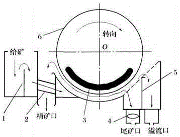
[0033] Such as figure 1 As shown, the magnetic separator for mines of the present invention includes a body. The body is provided with an accommodating cavity, and a relatively rotatable magnetic cylinder 6 is provided in the accommodating cavity, and a magnetic system 4 is provided in the magnetic cylinder 6 , One side of the containing cavity is provided with a concentrate port, and this side of the containing cavity is connected to a feed box through a feed pipe 2 which is connected to the fee...


PUM


Abstract

The invention discloses a magnetic separator for mines, and belongs to the field of mine machines. The magnetic separator for the mines comprises a separator body. A containing cavity is formed in the separator body. A magnetic drum capable of rotating relative to the containing cavity is arranged in the containing cavity. A magnetic system is arranged in the magnetic drum. A concentrate opening is formed in one side of the containing cavity, the side, provided with the concentrate opening, of the containing cavity is connected with a feeding box through an ore feeding pipe, and the ore feeding pipe penetrates through the concentrate opening to be connected to the feeding box. A tailing opening and an overflow opening are formed in the other side of the containing cavity. The concentrate opening is higher than an outlet of the ore feeding pipe, the tailing opening and the overflow opening. The rotating direction of the magnetic drum is opposite to the flowing direction of materials in the containing cavity. By means of the magnetic separator for the mines, the technical problems that the existing schreyerite extracting accuracy is not high, and sundries such as magnetite are many are mainly solved; due to opposite rotation of ore pulp and the magnetic drum, the rate for removing the magnetite in the ore pulp is increased, and therefore the schreyerite extracting accuracy is improved.

Description

Technical field [0001] The invention relates to the field of mining machinery, in particular to a magnetic separator for mining. Background technique [0002] In the mining process of mines, magnetic separators are often used to remove magnetic iron ore from the ore for reuse, etc., suitable for manganese ore, magnetite, pyrrhotite, roasted ore, ilmenite and other materials Magnetic separation operation. Among them, rare metals such as vanadium and titanium are contained in iron ore. Because of their scarcity, people often try to extract vanadium and titanium from iron ore as much as possible. At present, the commonly used method is to carry out multi-stage refinement treatment of the ore, and how long the screening can achieve the purpose of refining vanadium and titanium. The magnetic separator plays a vital role in removing magnetite from the mineral. The currently used magnetic separator is a general-purpose product and is not designed specifically for vanadium and titanium...

Claims


Application Information

Patent Timeline
IPC IPC(8): B03C1/12
Inventor 张荣斌
Owner 张荣斌
Learn More