Guiding mechanism for LED punching machine

A technology of guiding mechanism and punching machine, applied in metal processing equipment, feeding devices, manufacturing tools, etc., can solve the problems of warping deformation, incorrect position of LED bracket, no guiding mechanism of LED punching machine, etc., to achieve convenient docking, punching, etc. accurate effect

Inactive Publication Date: 2015-12-23
ANHUI ZHONGZHI LIGHT SOURCE TECH
View PDF0 Cites 0 Cited by
  • Summary
  • Abstract
  • Description
  • Claims
  • Application Information

AI Technical Summary

Problems solved by technology

[0003] The technical problem to be solved by the present invention is that the existing LED punching machine does not have a guiding mechanism, and the LED bracket may have hidden dangers such as misalignment, warping and deformation before punching, so a guiding mechanism for an LED punching machine is provided

Method used


Image

  • Guiding mechanism for LED punching machine

Examples


Embodiment Construction

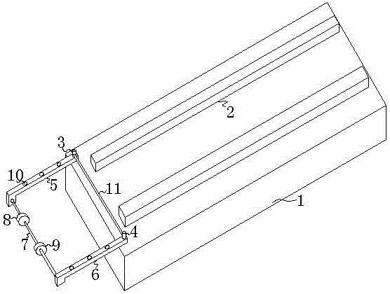
[0010] The present invention will be further described below in conjunction with the accompanying drawings.

[0011] Such as figure 1 As shown, the present invention includes a base 1 and a guide rail 2 affixed to the base, and the end of the outer base of the guide rail away from the stamping machine is movably connected with a horizontally rotatable left support rod through a left rotating shaft 3 and a right rotating shaft 4 respectively. 5 and the right support rod 6, the left support rod and the right support rod are symmetrical about the central axis of the base, and the ends of the left support rod and the right support rod are connected by a roller shaft 7, which is sleeved on the base The left limiter 8 and the right limiter 9 are symmetrically distributed in the center of the seat.

[0012] The base in the present invention is fixedly connected to the inlet end of the LED punching machine, and the guide rails include two guide rails that are symmetrical about the ce...


PUM


Abstract

The invention discloses a guiding mechanism for an LED punching machine. The guiding mechanism comprises a base (1) and guide rails (2) fixedly connected to the base. The ends, far away from the punching machine, of the parts, on the outer sides of the guide rails, of the base are movably connected with a horizontally-rotating left supporting rod (5) and a horizontally-rotating right supporting rod (6) through a left rotating shaft (3) and a right rotating shaft (4) respectively. The left supporting rod and the right supporting rod are symmetric about the central axis of the base. The tail end of the left supporting rod and the tail end of the right supporting rod are connected through a roll shaft (7). The roll shaft is sleeved with a left limiting block (8) and a right limiting block (9) which are symmetrically distributed about the central axis of the base. The guiding mechanism has the beneficial effects that an LED support to be punched is limited at the accurate position through the left limiting block and the right limiting block, accurate punching is guaranteed, the length of the parts, extending out of the base, of the left supporting rod and the right supporting rod can be adjusted through longitudinal through holes in the left supporting rod and the right supporting rod, and butt joint of the punching machine and an upper track procedure is facilitated. By means of a pressing rod, it can be prevented that the LED support warps when entering the guide rails, and punching work cannot proceed.

Description

technical field [0001] The invention relates to the field of LED technology, in particular to an LED stamping machine. Background technique [0002] At present, a general LED light source module consists of several LED chips welded on the substrate by patch or plug-in. The power of a single LED light-emitting element is 0.03-5W. The substrate is a PCB board, a flexible PCB board or aluminum, copper, etc. Metal substrates made of metal materials; or LED chips directly packaged on various substrates, commonly known as COB (chipson board). The above-mentioned substrates for fixing LED chips are designed with a heat dissipation structure, usually an aluminum substrate plus an aluminum profile heat sink, plus natural heat dissipation, air cooling or heat pipe heat dissipation, and semiconductor refrigeration for heat dissipation. The production process of LED light-emitting components is as follows: through all pre-cut metal substrates, plastic packaging is carried out on the me...

Claims


Application Information

Patent Timeline
Patent Type & Authority Applications(China)
IPC IPC(8): B21D43/00
Inventor 汪宗华徐林黄银青周逢海丁宁汪鹏王良生
Owner ANHUI ZHONGZHI LIGHT SOURCE TECH
Why Eureka
Try Eureka