Flying shear control system and control method based on machine vision

A flying shear control and machine vision technology, applied in the direction of shearing machine control device, shearing device, metal rolling, etc., can solve the problems of increasing the complexity and labor cost of the control system, avoid tediousness and irregularity, improve The effect of controlling precision

Active Publication Date: 2015-12-23
BEIJING BESTPOWER INTELCONTROL TECH CO LTD
View PDF5 Cites 14 Cited by
  • Summary
  • Abstract
  • Description
  • Claims
  • Application Information

AI Technical Summary

Problems solved by technology

However, this increases the complexit

Method used


Image

  • Flying shear control system and control method based on machine vision
  • Flying shear control system and control method based on machine vision
  • Flying shear control system and control method based on machine vision

Examples


Embodiment Construction

[0047]In order to enable those skilled in the art to better understand the solutions of the present invention, the following will clearly and completely describe the technical solutions in the embodiments of the present invention in conjunction with the drawings in the embodiments of the present invention. Obviously, the described embodiments are only It is an embodiment of a part of the present invention, but not all embodiments. Based on the embodiments of the present invention, all other embodiments obtained by persons of ordinary skill in the art without creative efforts shall fall within the protection scope of the present invention.

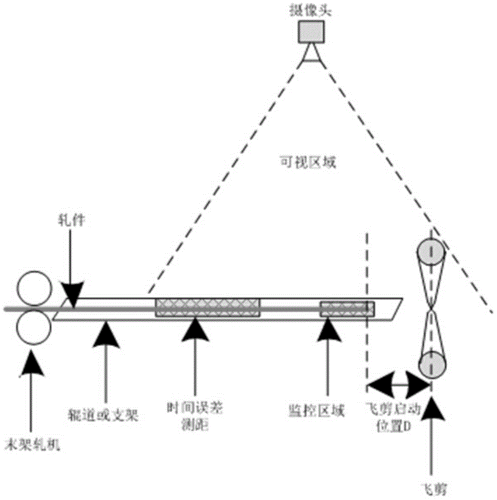
[0048] In the flying shear control system based on machine vision of the present invention, a camera is set between the flying shear and the roller table of the rolling mill, and the camera is perpendicular to the sky above the ground of the roller table, so that the flying shear is located in the image of the camera. However, in order to m...


PUM


Abstract

The invention provides a flying shear control system and control method based on machine vision. The controls system comprises a controller, flying shears, a camera, a rolling mill and a rolled piece located on a roller bed of the rolling mill. The camera is arranged between the flying shears and the rolling mill, and is located above the position perpendicular to the roller bed. The controller receives information from the camera. The controller controls and triggers the motion of the flying shears. The flying shears are located within the image range of the camera. The center line between the flying shears and the roller bed is aligned to the center line of an image of the camera. The color of a shear edge center line of the flying shears is different from surrounding background colors. The industrial high-speed camera is used for accurately measuring the position of the rolled piece and triggering the flying shears to be started, and the trouble and unregularity of a method that errors in the prior art can only be compensated by repeatedly testing and correcting factors are avoided. Control precision is improved, the flying shear control system and control method can automatically adapt to steel types of any specification and any piece rolling speed, and the parameters do not need to be tested or corrected.

Description

technical field [0001] The invention relates to the field of automatic control of steel rolling flying shears, in particular to a machine vision-based flying shears control system and a control method thereof. Background technique [0002] The function of rolling steel flying shear is to realize continuous fixed-length shearing or accidental broken shearing of rolling steel without stopping the running of the rolling mill. [0003] The rolling steel flying shear control system used in the prior art measures the speed of the rolling piece leaving the last stand by measuring the distance between two photoelectric cells and the time it takes for the rolling piece to pass through the two photoelectric cells in turn. Calculate the distance traveled by the rolling piece during the period from the start of the flying shear to the arrival at the shearing point. Calculate the delay time for the flying shear to start according to the predetermined length of the rolled piece to be cut...

Claims


Application Information

Patent Timeline
IPC IPC(8): B23D36/00B23D25/02B21B15/00
Inventor 李怡王会卿姜智伟杨天智张宏伟
Owner BEIJING BESTPOWER INTELCONTROL TECH CO LTD
Why Eureka
Try Eureka