Tire engine

A technology of engines and tires, applied in auxiliary drive devices, control devices, transportation and packaging, etc.

Inactive Publication Date: 2015-12-23
孙喜洲
View PDF6 Cites 0 Cited by
  • Summary
  • Abstract
  • Description
  • Claims
  • Application Information

AI Technical Summary

Problems solved by technology

[0004] The technical problem solved by the present invention is to change the deformation of the tire when the car is running into power that can be output. A tire with a certain vehicle quality will produce a certain deformation when it contacts the ground, and the extrusion force generated by the deformation is driven by the tire. The internal device absorbs and converts power output to the outside. The techn

Method used


Image

  • Tire engine
  • Tire engine

Examples


Embodiment Construction

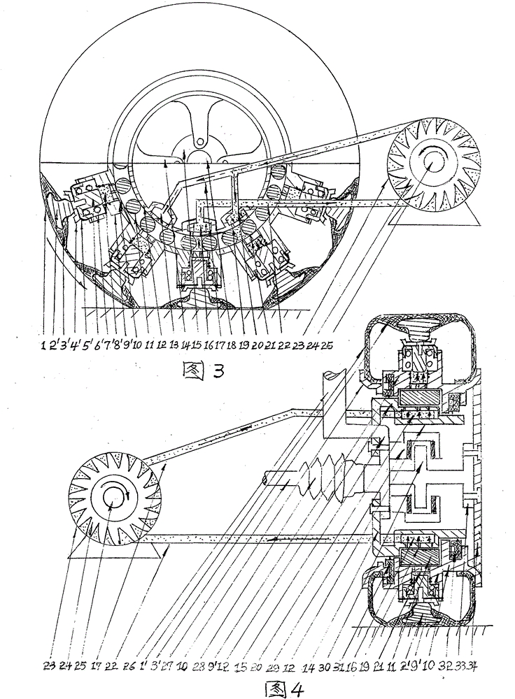
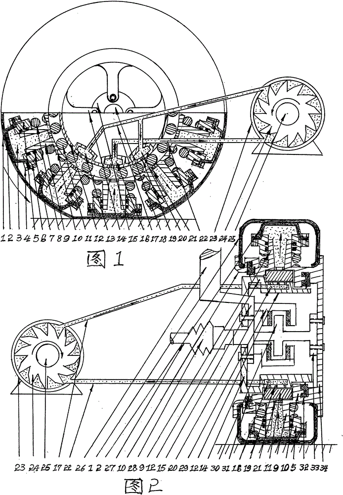
[0015] First install the drive shaft 27, universal joint 28, shock absorber 26, connecting plate 15, brake assembly 29, brake disc 30, and drive disc 33 of the original car, and then install the buffer tray on the sleeve 9 of the wheel hub 10 5. The buffer spring 8 sits on the upper end of the tray. The inner diameter of the tray is equipped with a sealing rubber ring 7 connected to the sleeve 9. The lower end of the tray presses the oil-resistant rubber tire 2 with the gland 4 through the bolt 6, and then installs the tire 1 on the On the rotating hub 10, if the hub of the nail-resistant stone road surface is installed, the piston 6', spring 7', diaphragm 5', and pressure plate 4' in the sleeve on the rotating hub 10 are installed, and then the push rod is installed. The tire 1 of 2′ is mounted on the rotating hub 10, and the rotating hub 10 is equipped with rolling steel balls 11, front oil seal 31 and rear oil seal 32. At this time, the fixed hub 12 and the rotating hub 10 a...


PUM


Abstract

Provided is a tire engine. Ten or N metal sleeves or sleeves capable of containing pistons are casted in a rotary hub; ten or N corresponding rubber bases capable of fixing pushing rods are casted in a tire matched with the piston sleeves; a fixed hub with an independent drive oil cavity and an oil return cavity is casted; the two hubs are spaced through a rolling bearing and forms a gap; when the tire makes contact with the ground and is perpendicular to the ground, squeezing force of deformation of the tire directly pushes oil-resisting rubber tires or the pistons to move upwards, and compression oil squeezed by the rubber tires or the pistons enters the drive oil cavity through oil guide holes and steel balls with the partition function, and enters an oil turbo machine through an oil inlet pipe to enable an impeller to rotate; returned oil of the other sleeve which releases pressure just now enables high-pressure oil to enter the oil returning cavity through an oil returning pipe and push the oil or the pistons to move downwards, oil resetting helps rotation of the impeller and power is output. A transmission shaft and a hub connection disc enable a wheel to rotate continuously, and if multiple wheels are staggered by a certain angle and rotate at the same time, force transmitted to the oil turbo machine can be output continuously to be used for generating electricity or the like.

Description

[0001] This "tire engine" is a device that can generate power by itself when the wheels are moving forward and output the power through the oil turbine for generator power generation or directly to the vehicle transmission system. The structural relationship of the tire engine is shown in the accompanying drawings. 1. Technical field [0002] The product of the invention can be used in the field of automobiles, motorcycles, bicycles and other motor vehicles and non-motor vehicles. As long as the wheels are walking on the ground, the device can be used to achieve the purpose of labor saving or power transmission. 2. Background technology [0003] As far as the current market is concerned, Guangfan uses fuel and gas-fueled engines as vehicle power. Because fossil fuels are unsustainable and pollute the environment, pure electric vehicles have been produced. However, due to the limitations of charging and driving range, for This has produced the invention of this device, and thi...

Claims


Application Information

Patent Timeline
IPC IPC(8): B60K25/08
Inventor 孙喜洲
Owner 孙喜洲
Why Eureka
Try Eureka