
A cutting machine for garment production

A cutting machine and clothing technology, applied in the field of clothing production, can solve the problems of wasting manpower, affecting the safety of operators, affecting processing work, etc., to improve the quality of finished products, avoid dust absorption, and increase stability.

Active Publication Date: 2018-08-31
SUZHOU GANNZ ELECTRONICS TECH CO LTD
View PDF5 Cites 0 Cited by
  • Summary
  • Abstract
  • Description
  • Claims
  • Application Information

AI Technical Summary

Problems solved by technology

There are mainly two ways to pick up the cut textiles: one is the most commonly used picking method, which uses manual picking up the cut textiles into the collection box, and then the handling trolley transports the collection box away. In the picking process, since the cutting machine is constantly cutting and conveying, it will affect the safety of the operator, and the entire picking efficiency is low, a lot of manpower is wasted, and the cost of production is increased; there is another kind of cutting and conveying through the belt conveyor belt. The cut textiles are transported to the designated processing workshop. This process does not require the operator to pick up the work, mainly through the belt. However, when the textiles are transported on the belt conveyor, the transport time is long, which affects the subsequent processing work, and Textiles exposed to the workshop for a long time will absorb certain dust and affect the quality of finished garments

Method used

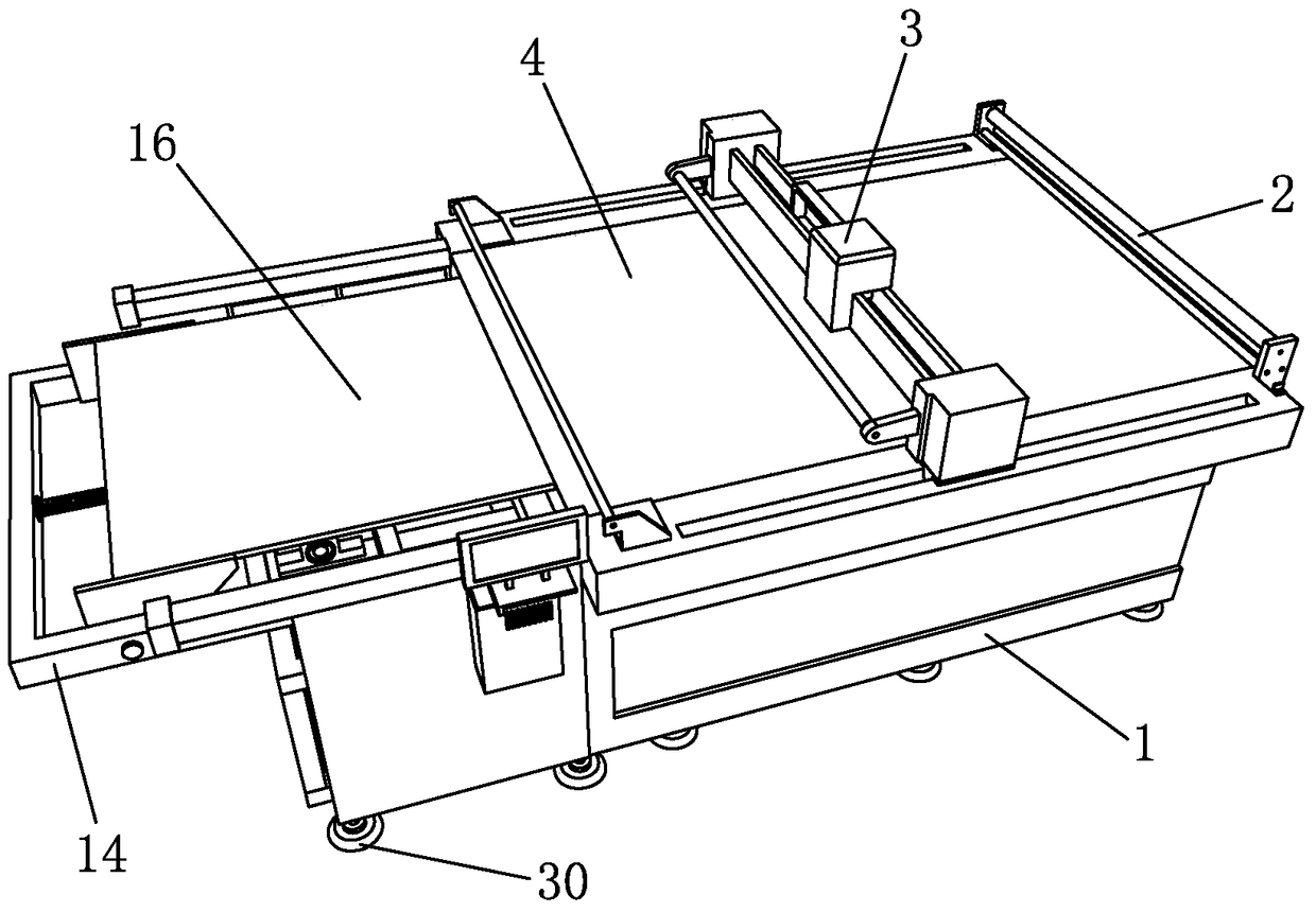

Image

  • A cutting machine for garment production
  • A cutting machine for garment production
  • A cutting machine for garment production

Examples


Embodiment Construction

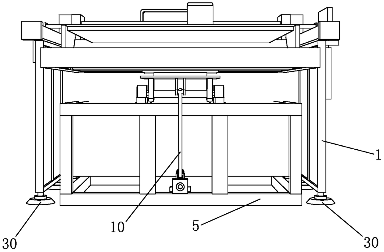
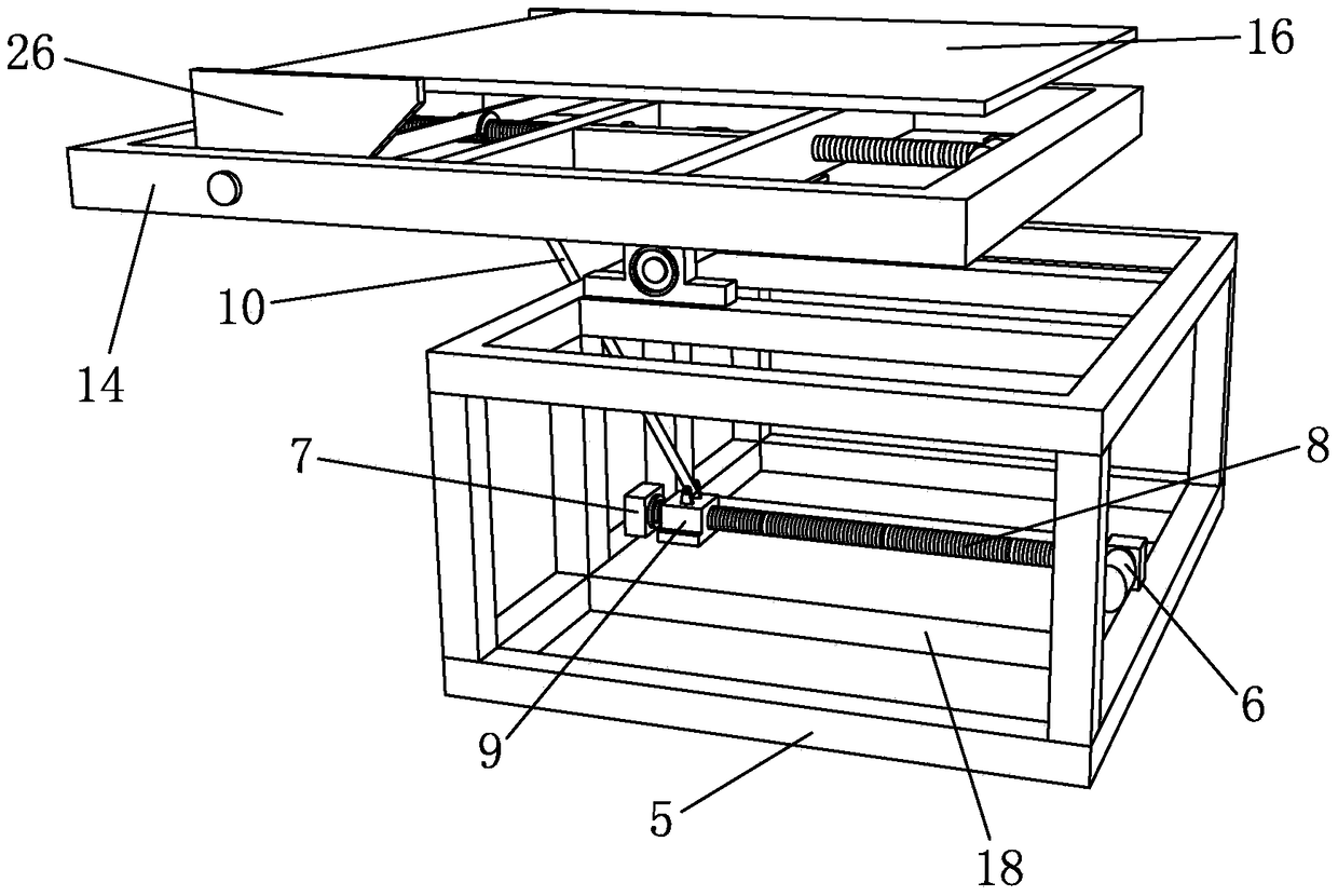
[0026] like Figure 1 to Figure 6 Shown is a cutting machine for garment production according to the present invention, which includes a frame 1 , an upper cloth frame 2 and a cutting mechanism 3 . The material of frame 1 should be made of light and high-strength materials as far as possible, generally made of aluminum alloy and ultra-thin steel plate. When frame 1 is in contact with the ground, the bottom of frame 1 will be slightly worn, and frame 1 is in contact with the ground. There will be a certain degree of slipping phenomenon on the ground, in order to prevent the occurrence of this type of phenomenon, to prolong the service life of the frame 1, the present invention is provided with a leg 30 at the bottom of the frame 1, the leg 30 supports the frame 1, and the frame 1 Raise a certain height, the support foot 30 is provided with anti-slip structure, the anti-slip structure adopts the aluminum core copper to wrap the hard rubber material outside, the hard rubber mater...


PUM


Abstract

The invention discloses a cutting machine for garment production, which comprises a frame, a cloth upper frame and a cutting mechanism, a conveying device is arranged on the frame, a discharge base is provided in the frame, and a driving device is provided on the discharge base , the driving device drives the slider to move on the slider; the slider is provided with a connecting rod, the unloading base is provided with a rotating base, and the rotating base is connected with a flip panel, and the flip panel is connected with the connecting rod; There is a "U"-shaped deck, the "U"-shaped deck is fixedly connected with a flip frame, and a leveling device is installed on the flip frame; the flip frame is rotatably connected with a discharge panel, the discharge panel and the conveying device The conveyor belts on the top are connected to each other, and the unloading panel is provided with a positioning plate, which is engaged with the leveling device. The invention realizes automatic picking up of the cut textiles, reduces labor force, and at the same time can collect the textiles into the collecting box at a relatively fast speed, prevents the textiles from absorbing dust, and improves the quality of finished garments.

Description

technical field [0001] The invention belongs to the technical field of garment production, in particular to a cutting machine for garment production. Background technique [0002] The garment and textile industry in my country is a highly labor-intensive and foreign-dependent industry. my country is the world's largest producer and exporter of textiles and clothing. The continuous and stable growth of textile and clothing exports is crucial to ensuring my country's foreign exchange reserves and balance of payments. , the stability of the RMB exchange rate, the solution to social employment and the sustainable development of the textile industry are crucial. At present, the general trend of the development of dyeing and finishing equipment technology at home and abroad is to develop in the direction of environmental protection, green, energy saving, low consumption, high efficiency and intelligence. [0003] At present, the cutting machine is a CNC cutting equipment used for ...

Claims


Application Information

Patent Timeline
Patent Type & Authority Patents(China)
IPC IPC(8): D06H7/00
Inventor 沈晨晖
Owner SUZHOU GANNZ ELECTRONICS TECH CO LTD
Learn More