Fireproof door for hydraulic power plant

A technology for fire doors and hydropower plants, which is applied to fire doors, door/window accessories, and wing handles, etc. It can solve problems such as difficulty in installation and movement, damage, and heavy weight, and achieve convenient transportation and installation and reduce labor. Excellent strength and fire resistance

Inactive Publication Date: 2015-12-23
CHONGQING SHUANGCHI DOORS & WINDOWS
View PDF0 Cites 0 Cited by
  • Summary
  • Abstract
  • Description
  • Claims
  • Application Information

AI Technical Summary

Problems solved by technology

[0003] In order to meet the load of power generation, the power generation equipment of large-scale hydropower plants is correspondingly large-scale equipment, and these large-scale power generation equipment will generate a lot of heat when doing work. The equipment is near the equipment to assist in power generation, and these equipment also need operators to operate to meet the production needs, and because of the presence of personnel on site, there may be combustible materials, so fire doors are needed to isolate the heat of the power generation equipment, and Some of the existing fire doors used in hydropower plants directly use iron sheets to wrap fireproof materials, but the strength of the iron sheets is not enough, and the fire doors will often be damaged after being used for a period of time, and the existing fire doors used for water The size of the fire doors of power plants is very large, generally as high as about 8 meters. If fireproof materials are directly added to the inside of the fire doors, the fireproof materials will easily break or fall from the upper part of the fire doors to the bottom, so that there will be gaps in the fire doors without fireproof materials. If there is no space, or the thickness of the fireproof material inside the fireproof door is different, which reduces the fireproof and heat insulation effect of the fireproof door, and if it is made of all steel plates, the weight is too large, which brings difficulties to installation and movement

Method used


Image

  • Fireproof door for hydraulic power plant

Examples


Embodiment Construction

[0014] The present invention will be described in further detail below by means of specific embodiments:

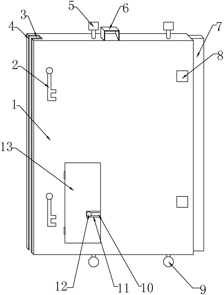
[0015] The reference signs in the drawings of the specification include: fire door body 1, hook 2, groove 3, rubber pad 4, roller 5, lifting lug 6, bump 7, fixed block 8, pulley 9, slide bar 10, bar Through groove 11, handle 12.

[0016] The embodiment is basically as attached figure 1 Shown: fire doors for hydroelectric power plants, including fire door body 1, the fire door body 1 is filled with fireproof cotton, the left side of the fire door body 1 has a groove 3, and the right side of the fire door body 1 is connected There is a bump 7 matching the groove 3, a hook 2 is hinged on the side wall of the fire door body 1 near the groove 3, and a fixing block 8 is connected to the side wall of the fire door body 1 near the bump 7 , the fixed block 8 has a hole, the upper end of the fire door body 1 is provided with a roller 5, the lower end of the fire door body 1 is pr...


PUM


Abstract

The invention relates to a fireproof door for a hydraulic power plant, and discloses a fireproof door for a hydraulic power plant. The fireproof door for the hydraulic power plant comprises a fireproof door body, wherein the fireproof door body is filled with fireproof cotton; a groove is formed in the left side of the fireproof door body; the right side of the fireproof door body is connected with a projection matched with the groove; the side wall of one side, which is close to the groove, of the fireproof door body is hinged to a hook; the side wall of the other side, which is close to the projection, of the fireproof door body is connected with a fixing block; and a hole is formed in the fixing block. The problem that the existing fireproof door for the hydraulic power plant is too heavy, and is mounted and moves difficultly is solved. The fireproof door for the hydraulic power plant is good in fireproof effect, light in weight and easy to mount, and moves easily.

Description

technical field [0001] The invention belongs to industrial fire doors, in particular to fire doors used in hydropower plants. Background technique [0002] Hydropower plants are referred to as hydropower plants for short. A hydropower plant is a factory that converts the potential energy and kinetic energy of water into electrical energy. The basic production process of a hydropower plant is: diverting water from a high place in a river or other reservoirs, using the pressure or flow velocity of the water to impel the turbine to rotate, The gravitational potential energy and kinetic energy are converted into mechanical energy, and then the water turbine drives the generator to rotate to convert the mechanical energy into electrical energy. [0003] In order to meet the load of power generation, the power generation equipment of large-scale hydropower plants is correspondingly large-scale equipment, and these large-scale power generation equipment will generate a lot of heat ...

Claims


Application Information

Patent Timeline
Patent Type & Authority Applications(China)
IPC IPC(8): E06B5/16E05D13/00E05B1/00
Inventor 文泉
Owner CHONGQING SHUANGCHI DOORS & WINDOWS
Why Eureka
Try Eureka