Efficient and powerful wire drawing reducer

A wire-drawing reducer, a strong type of technology, applied in transmission parts, components with teeth, belts/chains/gears, etc., can solve the problem that the input part cannot bear large radial loads, the poor working environment of the reducer, and the prevention of The oil leakage design is not ideal enough to achieve the effect of ensuring long-term safe operation, good oil leakage prevention effect and simple structure

Active Publication Date: 2017-09-08
ZHEJIANG TANHON DRIVING MACHINE
View PDF5 Cites 0 Cited by
  • Summary
  • Abstract
  • Description
  • Claims
  • Application Information

AI Technical Summary

Problems solved by technology

The main disadvantages of the above-mentioned reducer are: low transmission efficiency, weak impact resistance, the input part cannot withstand large radial loads, the anti-oil leakage design is not ideal, and the large vertical size leads to the high position of the wire drawing machine operating platform , there are potential safety hazards in the operation of the wire drawing machine. In addition, water will accumulate at the bottom of the installation flange, which will affect the seal at the top of the output shaft, and the accumulated water will easily enter the inside of the reducer and cause a bad working environment.

Method used


Image

  • Efficient and powerful wire drawing reducer

Examples


Embodiment Construction

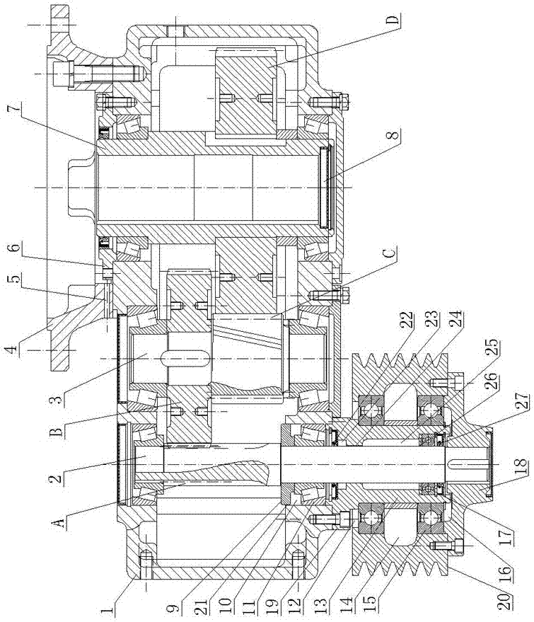
[0012] The present invention will be introduced and illustrated in detail below by specific embodiments:

[0013] As shown in the figure, the strong wire drawing reducer of the present invention includes a reduction box 1, an input shaft 2, an intermediate shaft 3 and an output shaft 7, the input shaft 2, the intermediate shaft 3 and the output shaft 7 are vertically arranged in parallel, and the input shaft The gear A provided on 2 meshes with the gear B provided on the intermediate shaft 3, the gear C provided on the intermediate shaft 3 meshes with the gear D provided on the output shaft 7, and the lower shaft end of the input shaft 2 passes through the reduction box 1 and The pulley 20 is connected, and the middle section of the input shaft 2 is slewing supported by the tapered roller bearing 11 installed in the bearing installation hole 10 of the reduction box body. The bearing end cover 19 of the tapered roller bearing 11 is fixedly installed at the bottom of the reductio...


PUM


Abstract

The invention discloses an efficient powerful wire drawing speed reducer which comprises a reduction gearbox body, an input shaft, an intermediate shaft and an output shaft. The input shaft is rotationally supported through a conical roller bearing installed in a bearing installation hole. A bearing end cover of the conical roller bearing is fixedly installed at the bottom of the reduction gearbox body. The efficient powerful wire drawing speed reducer is characterized in that a movable ring is arranged on the upper end face of the conical roller bearing, a first gap seal is formed between the outer circle of the movable ring and the bearing installation hole, the bearing end cover is provided with a lengthened sleeve, six seal combinations and a ball bearing are arranged between an inner hole of the sleeve and the outer circle of the input shaft from top to bottom, the lower shaft end of the input shaft is rotationally supported through the ball bearing, a belt wheel is rotationally arranged on the outer circle of the sleeve through rolling bearings, the bottom of the belt wheel is provided with a transmission disc fixedly connected with the belt wheel, and the transmission disc is in key connection with the lower shaft end of the input shaft. By the adoption of the efficient powerful wire drawing speed reducer, design is optimized, transmission efficiency is high, anti-impact capacity is high, oil leakage and water accumulation are prevented, the vertical size is small, and the input part can bear large radial loads due to the adoption of an unloading mechanism.

Description

technical field [0001] The invention relates to a reducer specially used for a wire drawing machine. Background technique [0002] In wire drawing and other industries, it is often applied to the flange-up installation type reducer of the parallel shaft series. The main features of the above-mentioned reducer are: the input shaft, the intermediate shaft and the output shaft are vertically arranged in parallel, and the top of the output shaft is installed The mounting flange with the opening upwards, the lower shaft end of the input shaft is connected with the pulley. The main disadvantages of the above-mentioned reducer are: low transmission efficiency, weak impact resistance, the input part cannot withstand large radial loads, the oil leakage prevention design is not ideal, and the large vertical size leads to the high position of the wire drawing machine operating platform , There are potential safety hazards in the operation of the wire drawing machine. In addition, wate...

Claims


Application Information

Patent Timeline
Patent Type & Authority Patents(China)
IPC IPC(8): F16H57/02F16H57/029F16H57/021F16H57/04
CPCF16H57/02F16H57/021F16H57/029F16H57/0412F16H2057/02039
Inventor 龚学华缪茂浪郑招业郑招雷柳圣杰
Owner ZHEJIANG TANHON DRIVING MACHINE
Why Eureka
Try Eureka