
High-temperature and high-pressure metal sealing ball valve

A metal sealing, high temperature and high pressure technology, applied in valve devices, cocks including cut-off devices, engine components, etc., can solve problems such as jamming, high temperature expansion of ball and valve seat, and floating valve seat loss of floating function. Flexible floating, anti-sedimentation, good running performance

Inactive Publication Date: 2015-12-23
应建忠
View PDF9 Cites 12 Cited by
  • Summary
  • Abstract
  • Description
  • Claims
  • Application Information

AI Technical Summary

Problems solved by technology

However, when the sealing device expands at high temperature, the space between the floating valve seat and the valve body will also expand radially to death, and the valve seat at the other end of the spring chamber and the valve body is sealed with a graphite sealing ring, and when the floating valve seat moves During the project, the radial wear of the graphite sealing ring will cause the medium particles to enter the spring cavity, causing the floating valve seat to lose its floating function, causing the ball and the valve seat to swell at high temperature or stuck at ultra-low temperature

Method used


Image

  • High-temperature and high-pressure metal sealing ball valve
  • High-temperature and high-pressure metal sealing ball valve

Examples


Embodiment Construction

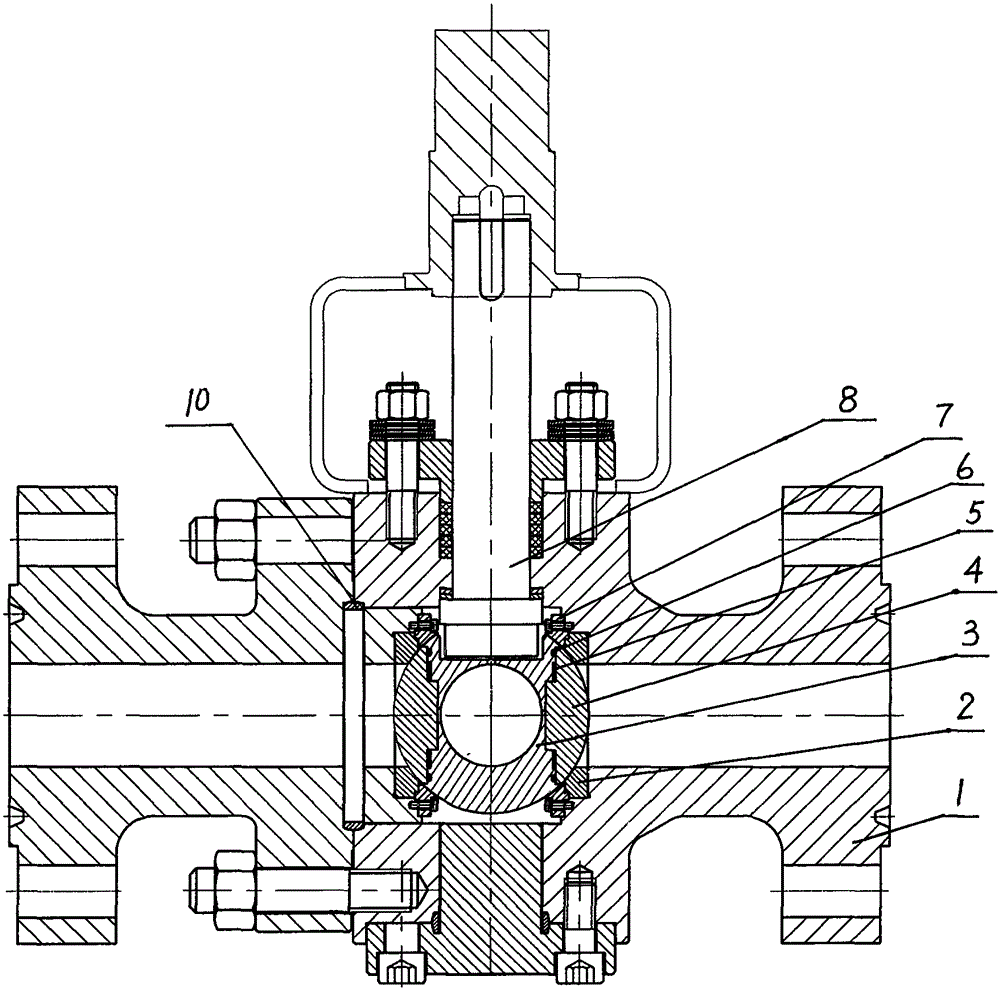
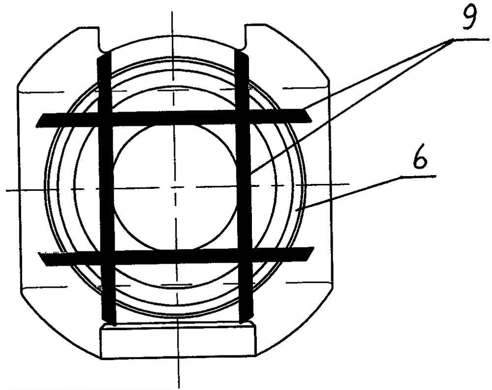
[0010] Such as figure 1 The high-temperature and high-pressure metal-sealed ball valve shown includes a valve body 1, a valve seat 2, a ball 3, and a valve stem 8. The valve seat 2 is respectively provided in the inlet and outlet channels of the valve body 1, and the diameter of the valve body 1 channel is made in the ball 3. Equal through holes, the sealing surface of the valve seat 2 and the surface of the sphere 3 are spray-welded with wear-resistant materials, and the inner surface of the through-hole of the sphere 3 is sprayed with wear-resistant materials; a plane is respectively made on the sphere 3 on both sides of the centerline of the through-hole of the sphere 3. The two planes are symmetrically arranged on the sphere 3 on both sides of the plane where the centerline of the valve stem 8 and the centerline of the through hole of the sphere 3 are located, and the three planes are parallel to each other, that is, the plane passing through the centerline of the valve ste...


PUM


Abstract

The invention relates to a high-temperature and high-pressure metal sealing ball valve. The high-temperature and high-pressure metal sealing ball valve comprises a valve body, a valve base, a sphere and a valve rod. Mainly, the potions, on the two sides of a center line of a sphere through hole, of the sphere are each provided with a plane; the planes on the two sides of the sphere are each internally provided with a ball clack; the ball clacks are in movable fit connection with round concave holes in the sphere through round convex columns; annular spring cavities and springs in the cavities are manufactured between the ball clack planes on the radial outer sides of the round convex columns and the sphere planes; annular anti-blocking grooves are manufactured in the portions, on the outer sides of the annular spring cavities, of the sphere planes; medium dredging grooves which lead to the outer surface of the sphere and are communicated with the annular anti-blocking grooves are manufactured in the portions, close to the spring cavities in the outer round faces of the round convex column, of the sphere planes; the valve base is fixedly installed in a valve body channel through a positioning ring; and a concave spherical face, matched with the sphere and the spherical faces of the ball clacks, of a positioning ball clack is manufactured on the positioning ring valve cavity side. The ball clacks of the high-temperature and high-pressure metal sealing ball valve are reliable in floatation, good in temperature resistance and suitable for the high-temperature and high-abrasion working condition of particle media.

Description

technical field [0001] The invention belongs to the field of valves, in particular to a metal hard-sealed ball valve. The invention is suitable for high temperature and high wear conditions of granular media. Background technique [0002] High-temperature hard-sealed ball valves are often used in high-temperature and high-wear media conditions. In order to prevent the valve seat and the ball from being stuck due to high-temperature expansion, floating valve seats are generally used to absorb the high-temperature expansion between the two, but the radial direction of the valve seat and the valve The spring cavity between the round walls in the body is easy to enter the medium particles and block it, so that the valve seat loses its floating function. For this reason, preventing the spring cavity from entering the medium becomes the key to product structure design and product performance assurance. For example, the scraper-type two-way high-temperature metal hard-sealed ball...

Claims


Application Information

Patent Timeline
IPC IPC(8): F16K5/06
CPCF16K5/06F16K5/0663
Inventor 应建忠
Owner 应建忠
Learn More