
Hydropower station floating trash discharge device

A floating, trash-blocking technology, which is applied in water conservancy projects, cleaning of open-air water surfaces, sea area engineering, etc., can solve the problems of complex vertical lifting pier head structure, simple structure, high investment cost, etc., to achieve good trash-blocking effect, The effect of flexible sliding and simple overall structure

Active Publication Date: 2021-12-24
CENTRAL SOUTH UNIVERSITY OF FORESTRY AND TECHNOLOGY
View PDF0 Cites 0 Cited by
  • Summary
  • Abstract
  • Description
  • Claims
  • Application Information

AI Technical Summary

Problems solved by technology

[0002] In water conservancy, hydropower and water intake projects, it is necessary to use slag and trash blocking devices to filter out floating or suspended solids in the water body. There are two types of trash rack and floating trash rack. The fixed trash rack anchors the anchor heads at both ends of the trash rack in the gate pier or pier. Its structure is simple but it cannot be adaptively floated with the water level of the inlet. , only suitable for hydropower stations with water level variation within a few meters; the floating trash rack connects one or both ends of the trash rack device to a movable trolley that can be lifted, and the vertical mobile trolley installed in the concave track of the fixed pier , to realize the up and down floating of the trash rack. The main body of the floating trash rack can float up and down with the change of the reservoir water level when the reservoir water level varies greatly. However, the vertical lifting pier head structure of the existing floating trash rack is complex , large amount of construction, relatively high investment cost

Method used


Image

  • Hydropower station floating trash discharge device
  • Hydropower station floating trash discharge device
  • Hydropower station floating trash discharge device

Examples


Embodiment Construction

[0025] The technical solutions in the embodiments of the present invention will be clearly and completely described below with reference to the accompanying drawings in the embodiments of the present invention. Obviously, the described embodiments are only a part of the embodiments of the present invention, but not all of the embodiments. Based on the embodiments of the present invention, all other embodiments obtained by those of ordinary skill in the art without creative efforts shall fall within the protection scope of the present invention.

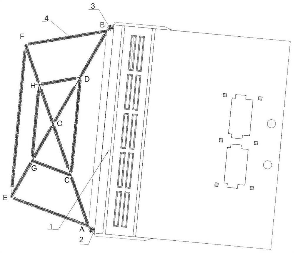
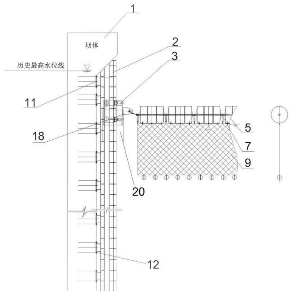
[0026] The floating sewage blocking and discharging device of the hydropower station includes two sliding rails 2. The sliding rails 2 are structured as follows Figure 5 As shown, the slide rail 2 includes side plates 11 with several threaded through holes, and the anchor rods 12 pass through the threaded through holes to connect the side plates 11 of the two slide rails 2 to the wall threads on both sides of the water inlet 1 of the ...


PUM


Abstract

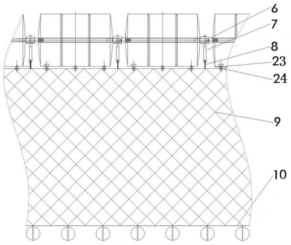
The invention discloses a floating waste-stopping device of a hydropower station, which comprises two slide rails, the two slide rails are respectively fixed on the walls on both sides of the water inlet of the dam, and a trolley is slidably connected to the two slide rails, and the trolley is connected to the two slide rails. The two ends of the truss structure are hinged, and the truss structure is formed by hinged ends of the float units. The bottom side of the truss structure is fixed with a trash net, and the bottom side of the trash net is fixed with heavy objects; the trash control device of the present invention has a simple structure and is convenient for installation and maintenance. , It can flexibly float up and down and adjust the structure with the change of water level, the stability of the trash blocking device is good, and the trash blocking efficiency is high.

Description

technical field [0001] The invention belongs to the technical field of floating slag blocking, and relates to a floating type silt blocking and discharging device for a hydropower station. Background technique [0002] In water conservancy, hydropower and water intake projects, it is necessary to use a slag and pollution-retaining device to filter out the floating or suspended matter in the water body. At present, the domestic slag-retaining and sewage-retaining device is mainly a movable slag-retaining and pollution-retaining device supported at both ends. There are two types of trash drains and floating trash drains. The fixed trash drains anchor the anchor heads at both ends of the trash drains in the gate pier or buttress. The structure is simple but cannot be adaptively floated with the change of the inlet water level. , only suitable for hydropower stations where the water level varies within a few meters; the floating sewage interception device connects one or both en...

Claims


Application Information

Patent Timeline
Patent Type & Authority Patents(China)
IPC IPC(8): E02B8/02E02B15/06
CPCE02B8/023E02B15/06
Inventor 陈爱军刘洋白帆贺国京
Owner CENTRAL SOUTH UNIVERSITY OF FORESTRY AND TECHNOLOGY
Learn More